Network and storage settings of ES NAS high-availability network storage services
Before the Setup
Purpose
This article is intended to guide users who have completed ES NAS installation and system initialization to configure network and storage settings for a high-availability storage environment.
Glossary
RAID group: RAID groups combine multiple physical hard disks into a logical unit to provide better capacity, read/write performance and/or protection.
Storage pool: Combines physical hard disks or RAID groups into large storage space. The ES NAS storage pool is created by adding a new RAID group, or adding hard disk to an existing storage pool.
Shared folder: Shared folders are created in a storage pool. They are used to store files that can be shared with users or groups with access rights.
NFS: Network File System (NFS) is a distributed file system protocol. The most important feature of NFS is that through network and mounting, it allows different devices with different operating systems to share files with each other. Through NFS, you can open an NFS Server-side directory or file system to NFS Client for data access. In other words, the NFS Client can mount the NFS Server's shared folder to the local host, so it can be easily manipulated as if operating on a local disk.
iSCSI LUN: iSCSI (Internet Small Computer System Interface) is a standard derived from Internet Protocol (IP) that can be used to link data storage devices. The program used to connect to the storage device is called an iSCSI initiator, and the connected device is collectively referred to as the iSCSI device or target. iSCSI LUNs are logical disks mounted to iSCSI target.
Host: Host refers to the device that is connected to the ES NAS for data access, or has mounted the ES NAS shared folder or iSCSI LUN to the local device.
System Deployment Architecture
The following figures and table shows the settings of a deployment example:
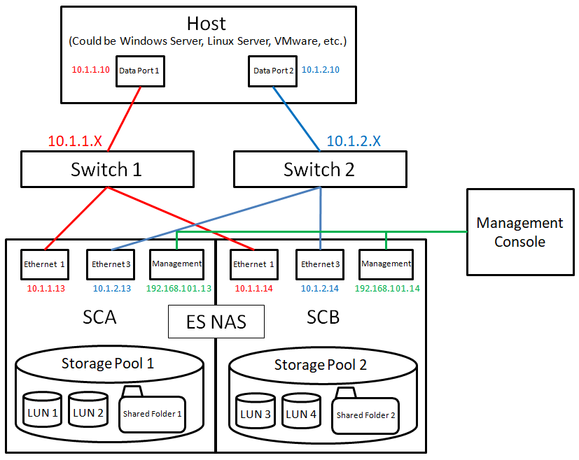
| ES NAS | ||
|---|---|---|
| Interface | IP Address | |
| SCA | SCB | |
| Management | 192.168.101.13 | 192.168.101.14 |
| Ethernet 1 | 10.1.1.13 | 10.1.1.14 |
| Ethernet 3 | 10.1.2.13 | 10.1.2.14 |
| Host | |
|---|---|
| Interface | IP Address |
| Data Port 1 | 10.1.1.10 |
| Data Port 2 | 10.1.2.10 |
Preparation before Setup
Before setting up the network environment and storage, make sure that you have completed the following tasks.
- Initialize the system drives.
- Update the firmware to the latest version.
- Log in to QES using a web browser.
To perform these tasks, refer to the ES NAS user guide and the QES user guide.
Network Environment Settings
Technical Overview
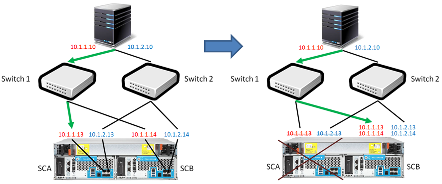
ES NAS places strong emphasis on high availability and failover, so network configuration is divided into two different use cases: "management" and "data transmission". ES NAS has two controllers, each with a management port and two data ports. The management port is used to open the QES desktop to manage the NAS using a web browser, and the data port is used for data access (such as Samba, NFS, and iSCSI). To achieve complete failover deployment, it is recommended that the data port on each controller be connected to a different network switch and that the data ports on both sides of the controller be configured with static IP addresses. For example, data port 1 of controller A should be set on the same subnet as data port 1 of controller B, and the same should be set for data port 2. As a result, when one controller fails, another controller will automatically take over. The server side can still connect to the controller that has taken over through the original IP address, so that the previous ongoing data access is continued.
Network Setup Steps
Follow the below steps to set up:
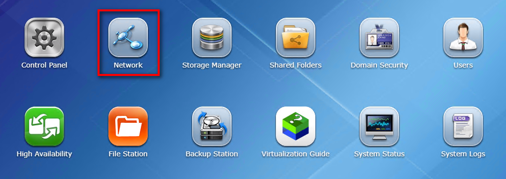
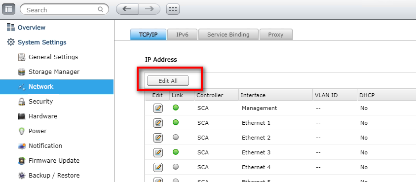
- After logging in to QES, click “Network” on the main menu.
- Click “Edit All”.
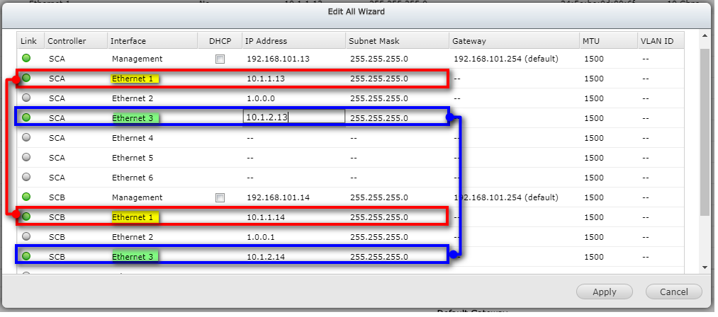
- Double-click the IP Address and Subnet Mask fields to modify the settings. If the Interface field displays “Management”, it is the management port. If it shows “Ethernet x”, it is a data port. Set the IP Address setting of SCA Ethernet x and SCB Ethernet x to the same subnet as the static IP. For example, if the IP Address setting of SCA Ethernet 3 is 10.1.2.13 with subnet mask of 255.255.255.0, set the IP address of SCB Ethernet 3 to 10.1.2.x, for example 10.1.2.14.
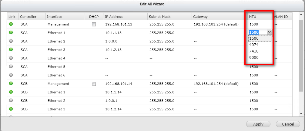
- If the existing network architecture supports Jumbo Frame settings, then select the appropriate MTU for the network environment. Maximum Transmission Unit (MTU) refers to the size (in bytes) of the largest packet that a given layer of a communications protocol can transmit. Adjusting this value increases the amount of Ethernet traffic and reduces CPU usage for large file transfers. The NAS uses standard Ethernet frame (1500 bytes) by default.
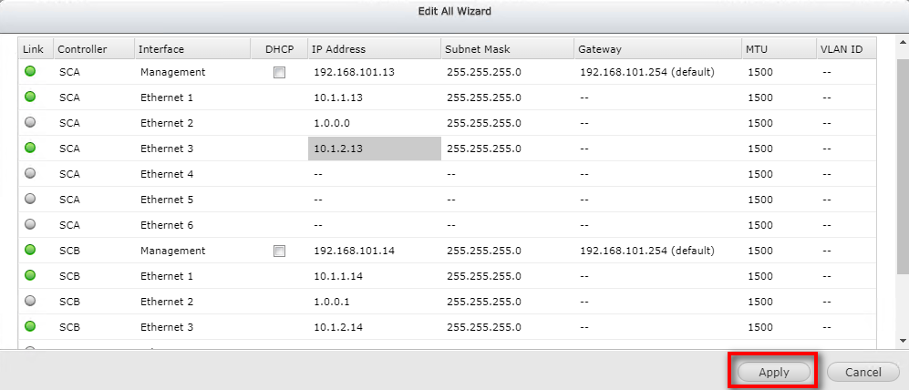
- Click “Apply” to complete the settings.
Storage Space Setup
Technical Overview
ES NAS uses the QNAP flexible storage space management architecture, which is divided into three layers: disk, storage pool, and shared folder / LUN. Users can build, expand and configure storage space flexibly and dynamically at all levels of the architecture according to different requirements, and maximize physical storage device efficiency.
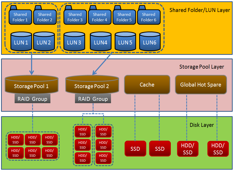
In addition, ES NAS uses dual active controller (Active-Active) storage system architecture. Besides providing fault-tolerant high-availability storage services, it is also different from the more common, single controller (Active-Standby / Active passive) architecture, as both controllers can be active at any time without wasting valuable hardware resources. It is recommended that users build multiple storage pools and distribute the storage pools evenly between controller A and controller B to take advantage of load balancing of the ES NAS dual active controller architecture.
Host List
The following steps will add hosts which connect to the ES NAS for data access or mount the shared folder or iSCSI LUN on the ES NAS to the local machine into the list. The Host list will be used in subsequent setup steps (Create a shared folder, Create an iSCSI Target and iSCSI LUN).
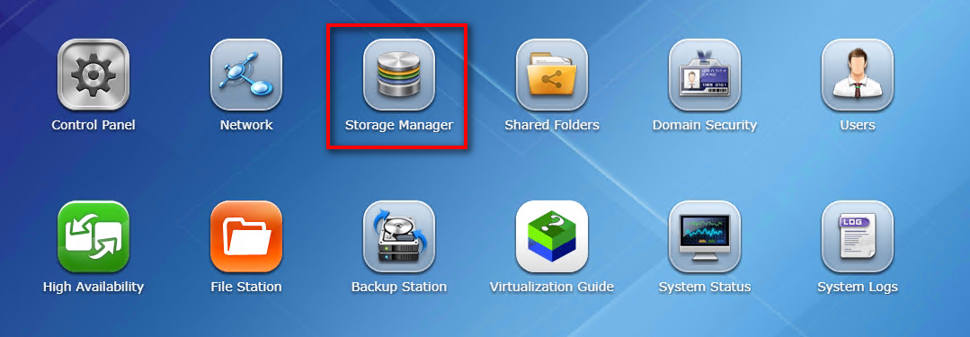
- Click "Storage Manager" on the main menu.
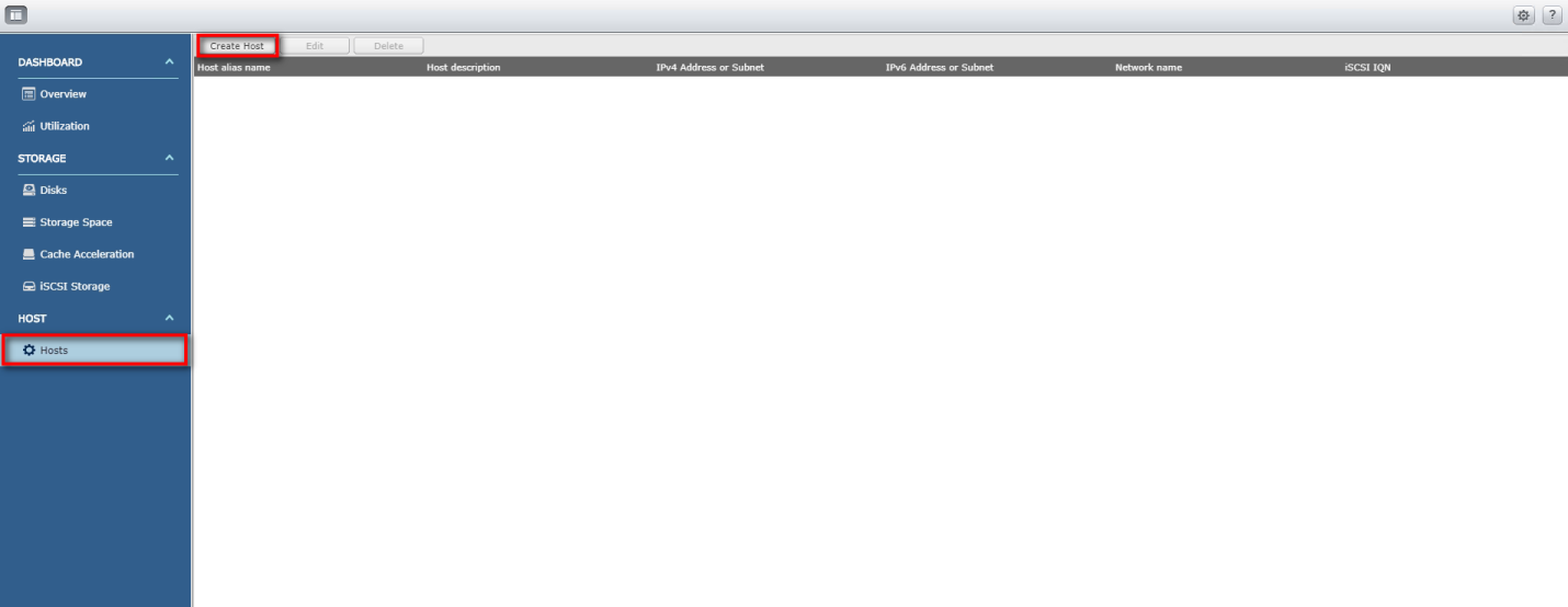
- In the left menu, click “Hosts”, then click “Create Host”.
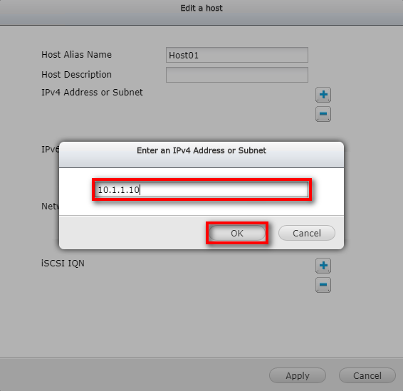
- Enter the name of the host you want to add in the "Host Alias Name" field and click “+” on the right of "IPv4 Address or Subnet".
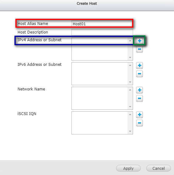
- Enter the port IP or subnet that will be used for data transfer between the Host and the ES NAS, and click “OK”. Please note that you can enter multiple IP addresses here. Set the IP to the same subnet as the ES NAS data port.
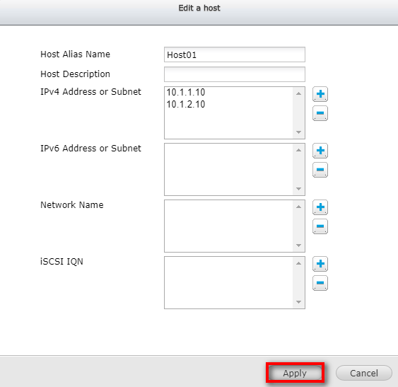
- When entering the IP addresses, click “Apply”.
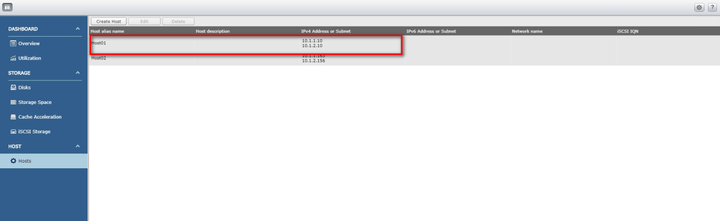
- Return to the "Hosts" page. You should be able to find the Host information just created on the list. Repeat the above steps to add multiple Hosts to the list.
Cache Acceleration
ES NAS supports SSD caching. When using SSD, it is recommended (but not necessary) to enable cache acceleration to significantly improve data access performance. Follow these steps to enable cache acceleration:
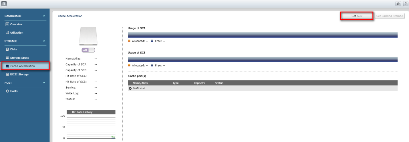
- Click "Storage Manager" on the main menu.
- In the left menu, click “Cache Acceleration”, then click “Set SSD”.
- Select the controller or expansion device where the SSD is located, and then select the SSD to be accelerated and click “OK”.
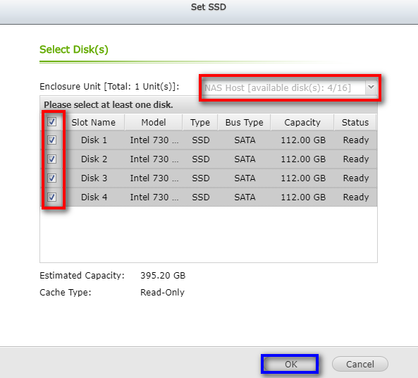
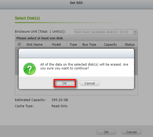
- As this action will erase all of the data on the SSD, you will be prompted to confirm your decision.
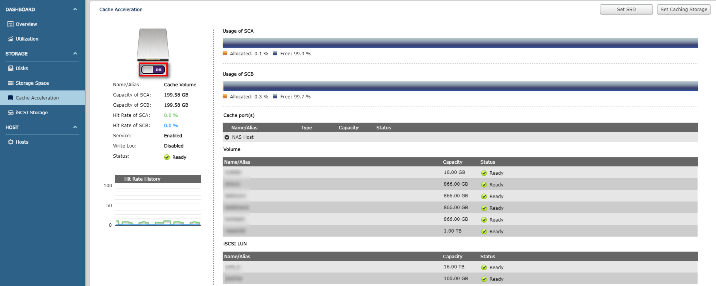
- When the settings are complete, go back to the "Cache Acceleration" page. The red box below should have a status of "on", indicating that cache acceleration is enabled.
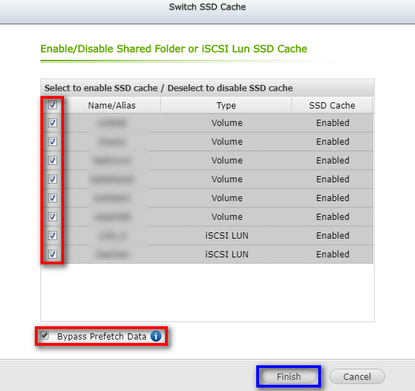
- To enable cache acceleration for individual shared folders or iSCSI LUNs, click “Set Caching Storage”.
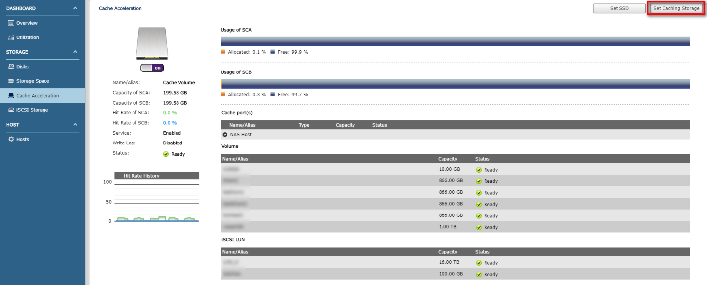
- Select the shared folders or iSCSI LUNs to enable/disable cache acceleration and select whether you want to perform large block and sequential I/O jobs in the cache space. For larger block, sequential I/O operations such as video streaming, the hit rate is lower, and by default, they are not recorded in the cache space. To record such jobs, uncheck “Bypass Prefetch Data”. Click "Finish" to complete the setting.
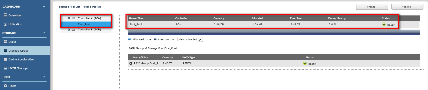
Add Storage Pool
- Click "Storage Manager" on the main menu.
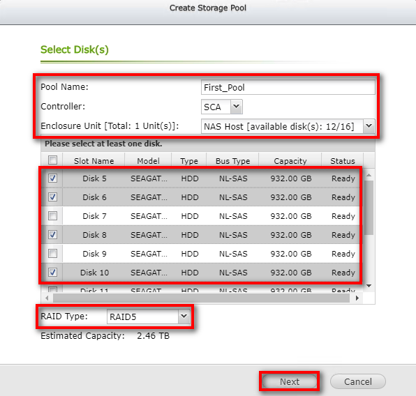
- In the left menu, click “Storage Space”, then click “Create”. In the drop-down menu, click “New Storage Pool”.

- Name the storage pool, select the controller and enclosure unit to which it belongs, and select the hard disk and RAID configuration for the new storage pool, then click “Next”. Please note that all of the data on the selected drives will be deleted.
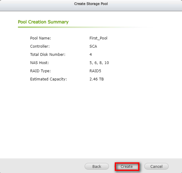
- Confirm the settings again, and then click “Create”.
- A confirmation window will appear. Click “OK”.
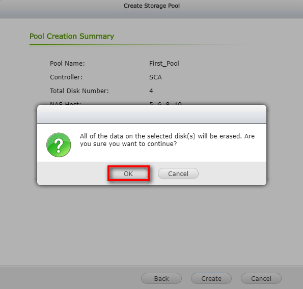
- A new storage pool is now created.
Expanding Storage Pools
To expand the storage pool capacity or create a RAID 50 or RAID 60 group, follow the below steps:
- Click "Storage Manager" on the main menu.
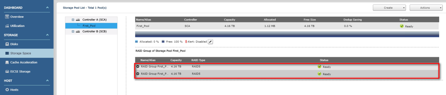
In the left menu, click “Storage Space”, then select the controller and the storage pool under the controller in the Storage Pool List, then click "Action” at the top right, and click "Expand Pool" in the drop-down menu.
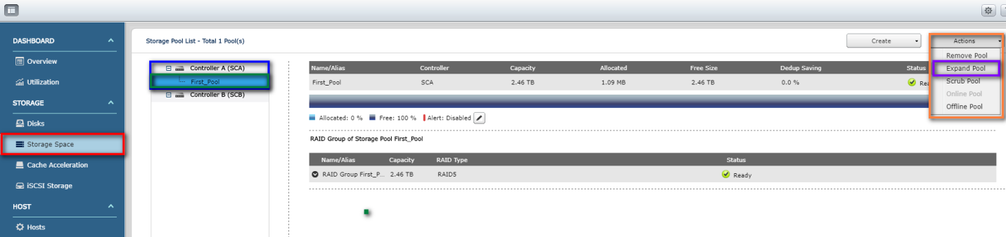
- Select the enclosure unit (you can also select the disk from the list of available hard disks) and click “Expand”. ES NAS uses parallel RAID groups to extend the storage pool, so the minimum number of hard disks to select is determined by the RAID configuration of the storage pool. For example, if the RAID configuration of the storage pool is RAID5, then the number of hard disks to expand must be at least three (the minimum number of disks for RAID 5), and the RAID configuration of the storage pool after expansion will be RAID 50. Similarly, if the RAID configuration of the storage pool is RAID 6, then you must select at least four hard disks (minimum number of disks for RAID 6), and the RAID configuration of the storage pool after expansion is RAID 60.
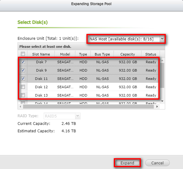
- A confirmation window will appear. Click “OK”.
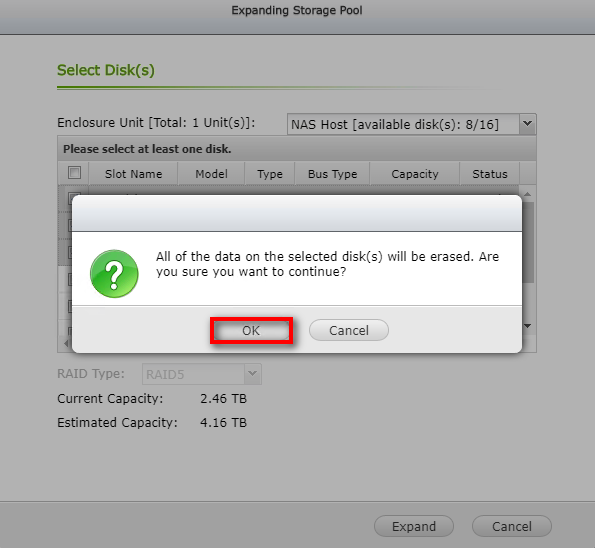
- The storage pool capacity is now expanded.
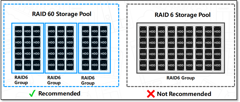
Increasing the number of disks in a RAID group increases the risk of simultaneous disk failure and lengthens rebuild times. When creating a storage pool with a large number of disks you should split the disks into sub-groups using RAID 50 or RAID 60.
- RAID 5 can tolerate 1 disk failure. The number of disks in a RAID 5 group should not exceed 9. For a greater number of disks use RAID 50.
- RAID 6 can tolerate 2 disk failures. The number of disks in a RAID 6 group should not exceed 16. For a greater number of disks use RAID 60.
Create a Shared Folder
Before you can create shared folders, the storage pool and data port must be set up.
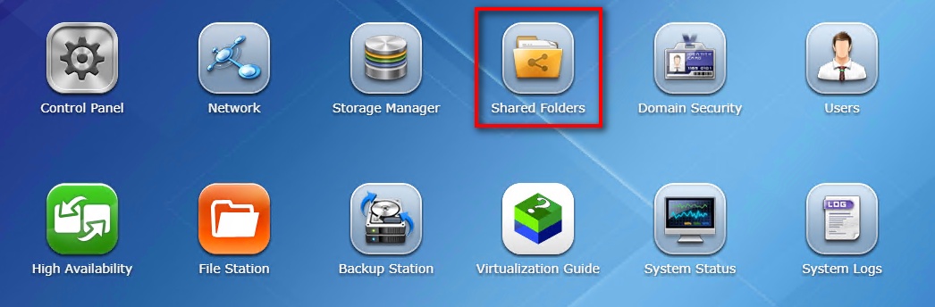
- On the main menu, click “Shared Folders”.
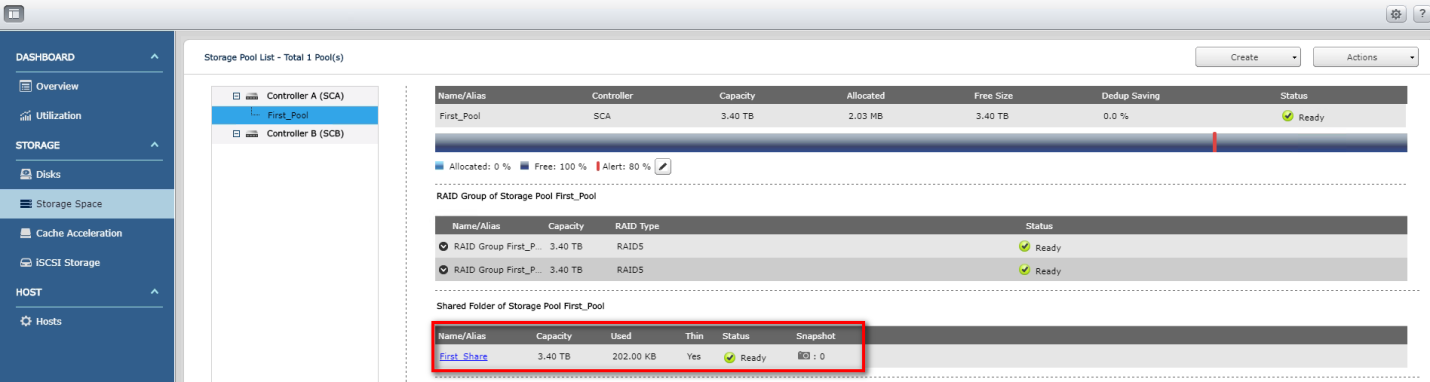
- In the Storage Pool List, select a storage pool, then click [Create] on the top right, and in the drop-down menu, click [New Shared Folder].

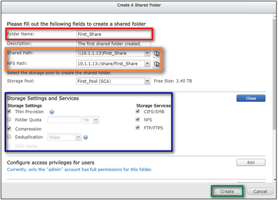
- Name the folder, view and copy the folder CIFS / SMB and NFS path in "Shared Path" and "NFS Path" respectively; then in "Storage Settings and Services", select the features according to the different application scenarios. The parameters are described below.
- Thin Provision: Allows the system to over-allocate the storage capacity regardless of the physical storage limit, and the physical disk space is used only when files are written into shared folders. It provides better space utilization.
- Folder Quota: Set the size of this shared folder. If not specified, the default is the maximum available space for the Pool.
- Compression: Data in the shared folder will be compressed to save storage space.
- Deduplication: Deduplication merges duplicate content in the shared folder to optimize disk space.
- SSD Cache: Frequently-accessed data in the shared folder will be placed in the SSD cache to improve access speed.
If there are no special requirements, retain the default values (under Storage Settings, keep the two options “Thin Provision” and “Compression” checked, and all options under Storage Services checked). Once the settings are confirmed, click “Create”.
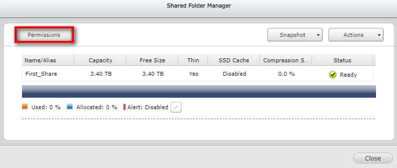
- The shared folder is created and appears in the list at the bottom-right of the “Storage Space” page. If the Host will mount or access this shared folder via NFS protocol, click the shared folder and continue with the following steps to set the permissions for the shared folder.
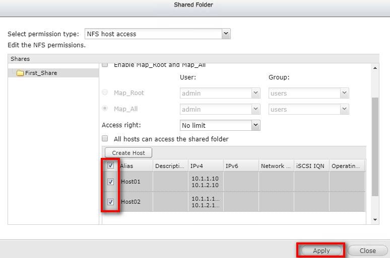
- Click “Permissions”.
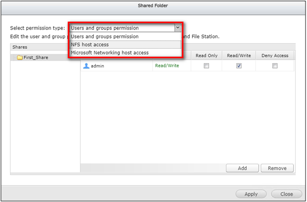
- Select “NFS host access” in the “Select permission type” drop-down menu.
- Select “No limit” in the “Access right” drop-down menu.
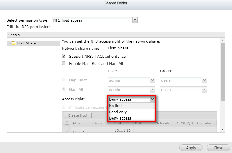
- Select the specified Host and click "Apply" to complete the setup.
Create an iSCSI Target and iSCSI LUN
- To create an iSCSI Target and iSCSI LUN, click "Storage Manager" on the main menu.
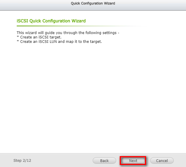
- In the left menu, click “iSCSI Storage”. You will be asked if you want to launch the quick configuration wizard. Click “OK”.
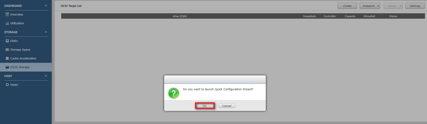
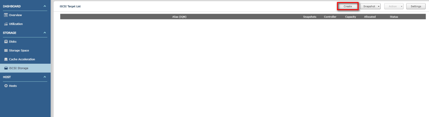
- If you click “Cancel” in the previous step, you can still start the iSCSI Storage Quick Configuration Wizard by clicking “Create” on the iSCSI Storage page.
- Select the iSCSI Target with a mapped LUN option and click “Next”.
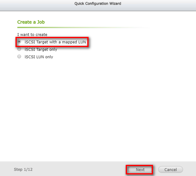
- Verify that you are creating an iSCSI Target and an iSCSI LUN mapped to the iSCSI Target. Click “Next”.
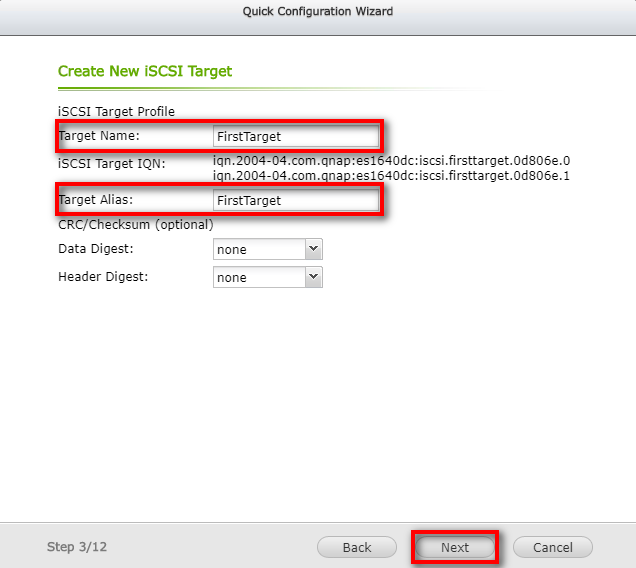
- Enter the name and alias of the iSCSI Target you want to create in the “Target Name” and “Target Alias fields” respectively. The CRC/Checksum below is the parameter used when the iSCSI initiator is connected to the iSCSI Target. This is an optional setting. When complete, click “Next”.
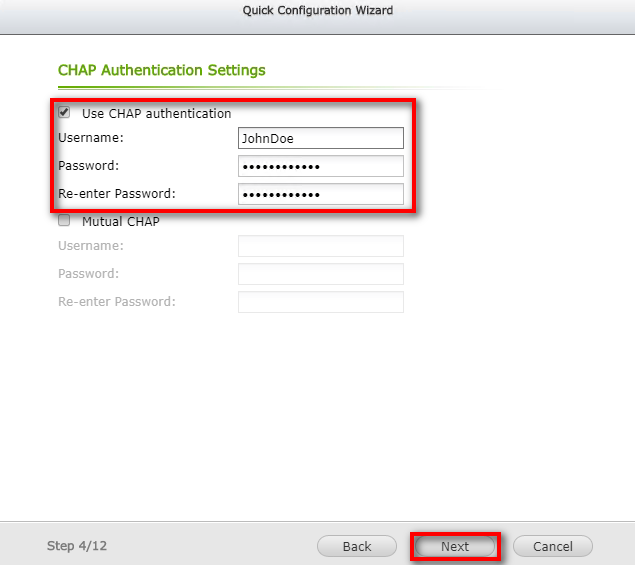
- If you need to use CHAP authentication, enter the account password, and click “Next”. If you do not need CHAP authentication, just click "Next”.
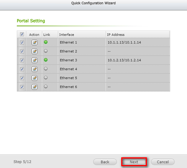
- Select the data ports you want to use for data transfer. If there are no special requirements, you can just use the default (all selected). Click "Next”.
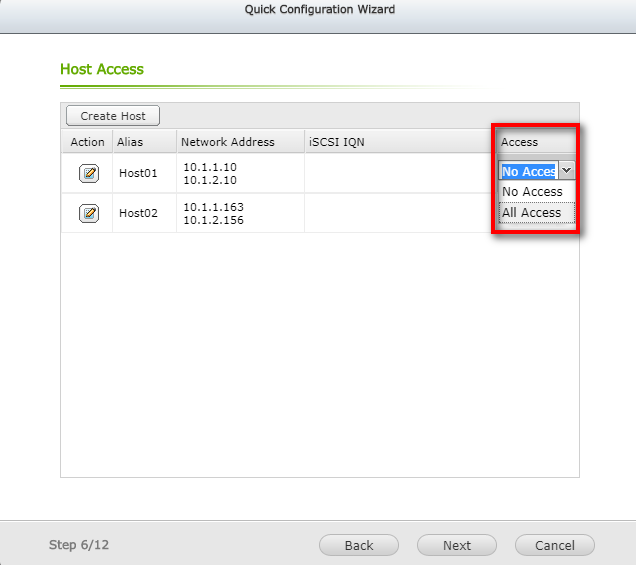
- Change the access rights of the specified Host to "All Access" in the list and click "Access" to modify the settings. Click "Next”.
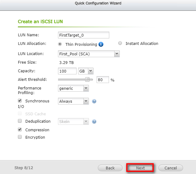
- In this step, you can modify the iSCSI LUN name, location (which will determine the default owner of this LUN as controller A or controller B), capacity, alert threshold, performance profiling and more. If you have no special requirements, just use the defaults and click “Next”.
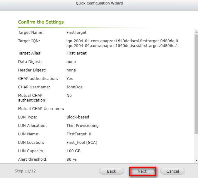
- Return to the configuration. If it is correct, click “Next”. If it is incorrect, click “Back” to return to the previous step to modify the configuration.
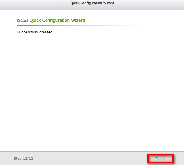
- After completion, click “Finish” to exit the wizard.
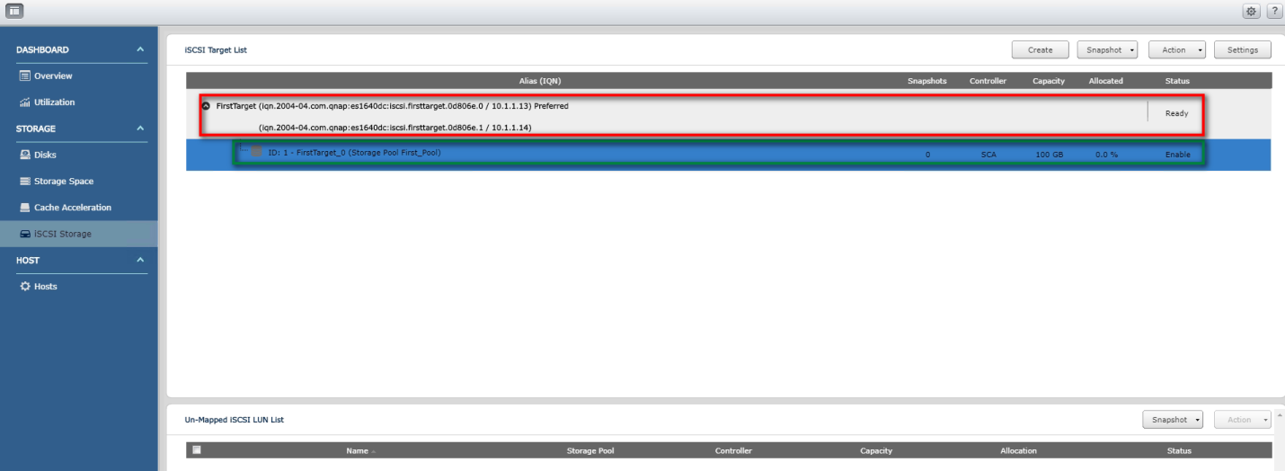
- Return to the iSCSI Storage page. In the iSCSI Target List, you will see the iSCSI Target you just created. Double-click the iSCSI Target and the iSCSI LUN you just created will show below. This means that the iSCSI Target and iSCSI LUN have been created successfully. Under each Target, you will see two iqn, representing the target is created on controller A and controller B (iqn ending with.0 is controller A,.1 is controller B) respectively, and the word "Preferred" at the end means that the Target is the default optimal IO path. Therefore, a LUN mounted on a Target with controller A as Preferred default will not be able to be mounted on a Target with controller B as the default. Similarly, a LUN mounted on a Target with controller B as Preferred default will not be able to be mounted on a Target with controller A as the default.