Applicable Products
Hardware
- QSW-M7308R-4X
- QSW-M3224-24T
Software
Details
Multichassis link aggregation (MC-LAG) allows two switches to operate as a single logical switch. It uses a peer link between the switches to coordinate traffic and link aggregation groups (LAGs) to combine multiple physical ports for redundancy and load sharing.
For NAS devices, MC-LAG enables connections to either switch while maintaining a single aggregated link. This provides redundancy (connections remain active if one switch fails), higher bandwidth (multiple NAS ports aggregated across switches), and load balancing across all member ports, ensuring resilient, high-performance storage access.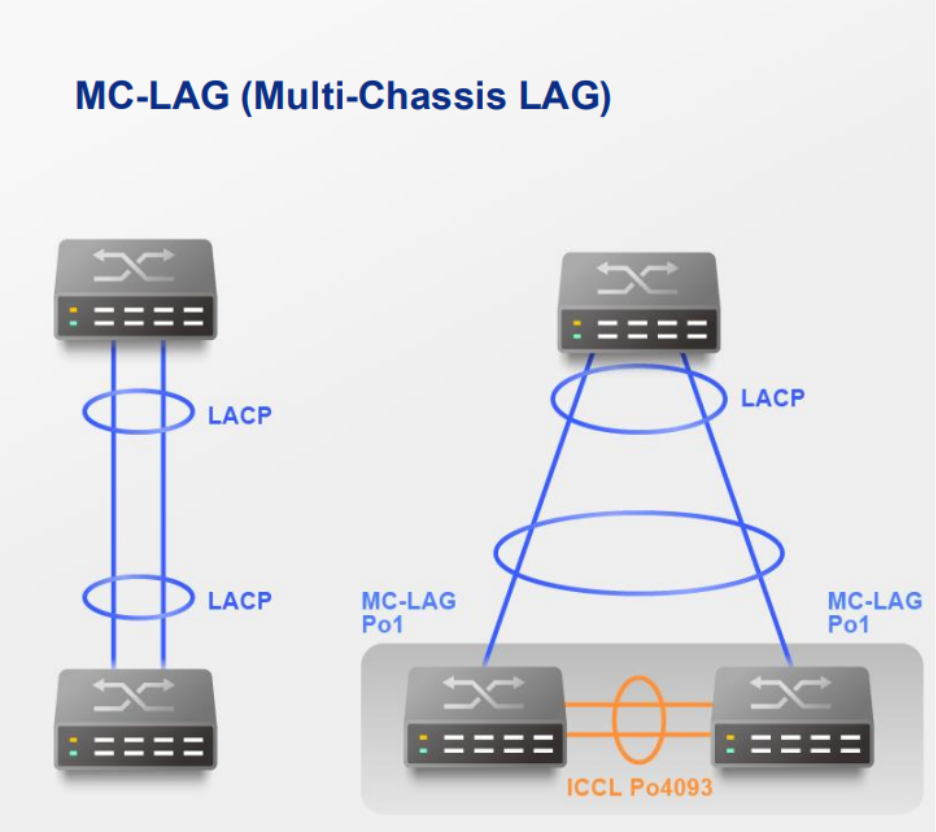
Procedure
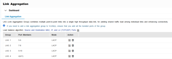
A. Configure LAG groups
Important
Ensure that you configure the LAG before connecting cables to the switch to avoid creating a data loop.
- Log in to the switch system.
- Go to L2 Features > Link Aggregation.
- Identify a group.
- Click
 .
.
The Edit Group window appears. - Configure the group settings.
| Setting | Description |
|---|
| Mode | Controls the link aggregation mode for the group.
Select LACP to ensure automatic negotiation and failover for stable MC-LAG operation. |
| Port Configuration | Specifies which ports are included in the group Note Ensure that you configure the same settings for all the member ports in a LAG. |
- Click Save.
Note
Make sure the same LAGs are configured on both switches.
B. Configure MC-LAG settings
- Log in to the switch system.
- Click MC-LAG.
- Click Settings.
The MC-LAG Settings window appears.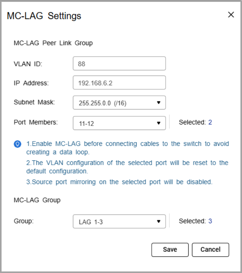
- Specify the VLAN ID.
Use the same VLAN on both switches. This VLAN is reserved for the peer link. - Specify the IP address for inter-chassis control protocol (ICCP) communication.
Assign the peer link IP address within the same subnet as the other switch, using a VLAN other than VLAN 1. - Specify the IP subnet mask.
The subnet mask must match on both switches. - Select one or more member ports.
Assign at least two ports for redundancy. - Select one or more link aggregation groups (MC-LAG group).
Note
Use the LAGs created earlier, and ensure the same LAG IDs are configured on both switches.
- Click Save.
The switch saves the MC-LAG configuration. - On the MC-LAG page, click Enable.
The switch enables MC-LAG. - Configure the MC-LAG settings on the peer switch.
- Reboot both switches.
C. Verify configuration
- Check MC-LAG status in the settings page.
- Verify the peer link and member ports are active.
Connection Guide
- Enable port trunking on the QNAP NAS.
For details, see "Configuring port trunking settings" in the QTS User Guide or QuTS hero User Guide. - Connect each NAS network port to switch ports that are members of the same LAG ID on both switches.
If the NAS trunk group is assigned to LAG 1, NAS port 1 can connect to a LAG 1 member port on switch A, and NAS port 2 can connect to a LAG 1 member port on switch B.Note
The NAS ports in the trunk can either connect to the same switch or be split across the two MC-LAG peer switches. In both cases, the ports must belong to the same LAG ID
- Verify the connection.
- On the NAS, confirm that the port trunking group shows all member ports as active.
- On the switches, check that the assigned LAG connection is active and monitoring traffic.
Example Topology
Two switches are configured in an MC-LAG cluster, allowing them to operate as a single logical switch. The switches coordinate traffic over a peer link and use link aggregation groups (LAGs) to combine multiple physical ports for redundancy and load sharing.
Multiple NAS devices can connect to the cluster using link aggregation. Each NAS can distribute its network ports across both switches. For example, one NAS port can connect to switch A and another port can connect to switch B, while still maintaining a single aggregated connection.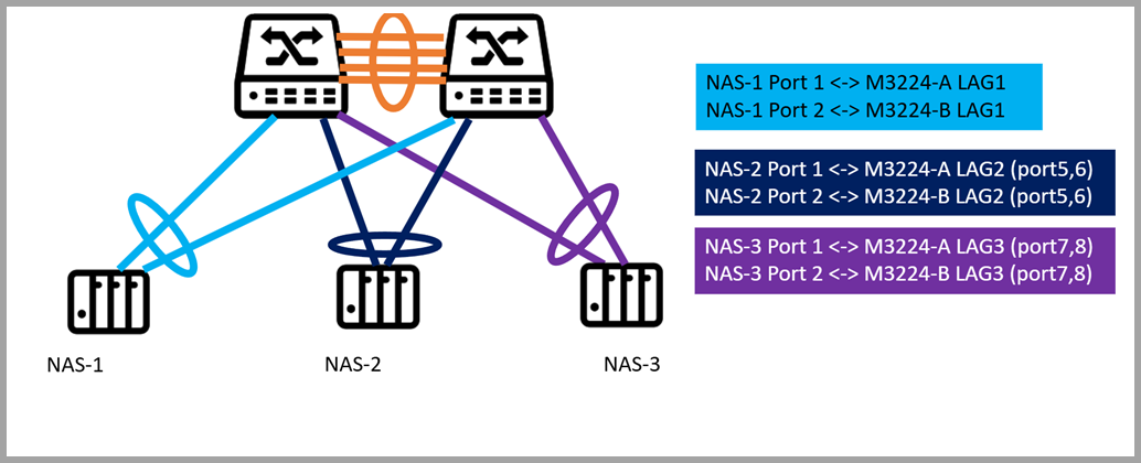
Each NAS is connected to two switches (QSW-M3224-A and QSW-M3224-B) using port trunking. The connections are grouped via dynamic link aggregation (LAG) as follows:
- NAS-1 -> LAG1: Ports 1 and 2 on both switches
- NAS-2 -> LAG2: Ports 5 and 6 on both switches
- NAS-3 -> LAG3: Ports 7 and 8 on both switches
Note
"A" and "B" indicate the respective switches. Each LAG spans both switches to provide redundancy and load balancing.
From the network perspective, the MC-LAG cluster ensures that if one switch or a single port fails, the NAS continues to communicate through the remaining switch, providing uninterrupted access to storage. Traffic is automatically load balanced across all LAG member ports, maximizing throughput and avoiding bottlenecks.
For NAS users, this configuration simplifies network management, improves performance, and provides resilient, high-availability storage access without requiring complex failover setup.
Further Reading
适用产品
硬件
- QSW-M7308R-4X
- QSW-M3224-24T
软件
详情
多机箱链路聚合(MC-LAG)允许两个交换机作为一个逻辑交换机运行。它使用交换机之间的对等链路来协调流量,并使用链路聚合组(LAG)来组合多个物理端口以实现冗余和负载共享。
对于 NAS 设备,MC-LAG 支持连接到任意交换机,同时保持单个聚合链路。这提供了冗余(如果一个交换机故障,连接仍然保持活跃)、更高的带宽(多个 NAS 端口跨交换机聚合),以及所有成员端口上的负载平衡,确保可靠的高性能存储访问。
步骤
A. 配置 LAG 组
重要提示
确保在连接电缆到交换机之前配置 LAG,以避免创建数据环路。
- 登录交换机系统。
- 进入L2 功能>链路聚合。
- 识别一个组。
- 点击。
出现编辑组窗口。 - 配置组设置。
| 设置 | 描述 |
|---|
| 模式 | 控制组的链路聚合模式。
选择LACP以确保自动协商和故障转移以稳定 MC-LAG 操作。 |
| 端口配置 | 指定组中包含哪些端口 注意 确保为 LAG 中的所有成员端口配置相同的设置。 |
- 点击保存。
B. 配置 MC-LAG 设置
- 登录交换机系统。
- 点击MC-LAG。
- 点击设置。
出现MC-LAG 设置窗口。 - 指定 VLAN ID。
在两个交换机上使用相同的 VLAN。此 VLAN 保留用于对等链路。 - 指定用于机箱间控制协议(ICCP)通信的 IP 地址。
在与另一交换机相同的子网内分配对等链路 IP 地址,使用除 VLAN 1 以外的 VLAN。 - 指定 IP 子网掩码。
子网掩码必须在两个交换机上匹配。 - 选择一个或多个成员端口。
分配至少两个端口以确保冗余。 - 选择一个或多个链路聚合组(MC-LAG 组)。
注意
使用之前创建的 LAG,并确保在两个交换机上配置相同的 LAG ID。
- 点击保存。
交换机保存 MC-LAG 配置。 - 在 MC-LAG 页面上,点击启用。
交换机启用 MC-LAG。 - 在对等交换机上配置 MC-LAG 设置。
- 重启两个交换机。
C. 验证配置
- 在设置页面检查 MC-LAG 状态。
- 验证对等链路和成员端口是否处于活动状态。
连接指南
- 在 QNAP NAS 上启用端口中继。
详情请参阅QTS 用户指南或QuTS hero 用户指南中的“配置端口中继设置”。 - 将每个 NAS 网络端口连接到两个交换机上属于相同 LAG ID 的交换机端口。
如果 NAS 中继组分配给 LAG 1,NAS 端口 1 可以连接到交换机 A 上的 LAG 1 成员端口,NAS 端口 2 可以连接到交换机 B 上的 LAG 1 成员端口。注意
中继中的 NAS 端口可以连接到同一个交换机或分布在两个 MC-LAG 对等交换机之间。在这两种情况下,端口必须属于相同的 LAG ID
- 验证连接。
- 在 NAS 上确认端口中继组显示所有成员端口为活动状态。
- 在交换机上检查分配的 LAG 连接是否处于活动状态并监控流量。
示例拓扑
两个交换机配置在一个 MC-LAG 群集中,使它们能够作为一个逻辑交换机运行。交换机通过对等链路协调流量,并使用链路聚合组(LAG)将多个物理端口组合以实现冗余和负载共享。
多个 NAS 设备可以使用链路聚合连接到群集。每个 NAS 可以将其网络端口分布在两个交换机上。例如,一个 NAS 端口可以连接到交换机 A,另一个端口可以连接到交换机 B,同时仍保持单一聚合连接。
每个 NAS 通过端口中继连接到两个交换机(QSW-M3224- A 和 QSW-M3224-B)。连接通过动态链路聚合(LAG)分组如下:
- NAS-1 -> LAG1:两个交换机上的端口 1 和端口 2
- NAS-2 -> LAG2:两个交换机上的端口 5 和端口 6
- NAS-3 -> LAG3:两个交换机上的端口 7 和端口 8
注意
“A”和“B”表示各自的交换机。每个 LAG 跨越两个交换机以提供冗余和负载平衡。
从网络角度来看,MC-LAG 群集确保如果一个交换机或单个端口发生故障,NAS 仍能通过剩余的交换机进行通信,提供不间断的存储访问。流量自动在所有 LAG 成员端口之间负载均衡,优化吞吐量并避免瓶颈。
对于 NAS 用户来说,这种配置简化了网络管理,提升了性能,并提供了弹性、高可用性的存储访问,而无需复杂的故障转移设置。
进一步阅读


