VMware - Configuring iSCSI Datastore with QNAP QES
Category
- VMware:
vSphere Web Client html5 for 7 and 6.7, vSphere Web Client 6.5, vSphere Web Client 6.0, and vSphere windows version - Storage device:
QES version 1.1.4 ~ 2.1.1 - NAS model:
ES2486dc, ES1686dc, ES1640dc v2, ES1640dc
VMware and iSCSI Architecture
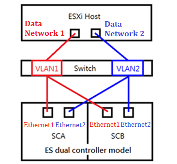
To use iSCSI Storage Area Networks (SAN), create a LUN on the iSCSI target (for example: the QES NAS) and mount it as a datastore on a host. The following diagram illustrates the deployment of iSCSI storage in a vSphere environment.
Note:
1 Gigabit Ethernet (1GbE) (or higher) is recommended for use in connecting to an iSCSI target.
Preparation for Installation
ESXi hosts are able to connect to the QES NAS via iSCSI. You can set up datastores (repositories for virtual machines) on the QES NAS that the ESXi hosts discover in your vSphere environment. The application tutorial will demonstrate the implementation.
- IP addressing: Static IP addresses are recommended for both ESXi hosts and the QES NAS.
Confirm these details before configuration
- All data ports, from the ESXi host and the QES NAS, should be in the same subnet.
- Available pools must be built before configuring iSCSI LUN on the QES NAS. For more information on creating a storage pool, read Network and Storage Settings of QES NAS High-Availability Network Storage Services.
Definition
In this document, the VMware ESXi host is defined as the iSCSI Initiator, and the QES NAS is the iSCSI Target.
For VMware vSphere Web Client HTML5
Server and Storage Network Settings
|
Server Network Settings |
||
|---|---|---|
|
Role |
IP |
Description |
|
ESXi host |
192.168.217.2 |
VMware ESXi host |
|
Data Network 1 |
10.30.10.2 |
10G Data port 1 in ESXi host |
|
Data Network 2 |
10.40.20.2 |
10G Data port 2 in ESXi host |
|
Storage Network Settings |
||
|---|---|---|
|
Setting |
Value |
Description |
|
SCA Management IP |
192.168.217.41 |
Management IP of controller A |
|
SCA Ethernet1 IP |
10.30.10.41 |
Data port 1 IP of controller A |
|
SCA Ethernet2 IP |
10.40.10.41 |
Data port 2 IP of controller A |
|
SCB Management IP |
192.168.217.42 |
Management IP of controller B |
|
SCB Ethernet1 IP |
10.30.10.42 |
Data port 1 IP of controller B |
|
SCB Ethernet2 IP |
10.40.10.42 |
Data port 2 IP of controller B |
|
Pool allocate to SCB |
Pool2 |
RAID6 pool at controller B |
With the information listed in the above table, assuming a 100GB LUN is deployed on ES dual controller B (SCB), it can be mounted using the following steps on the ESXi host.
Add iSCSI Targets on VMware ESXi Hosts
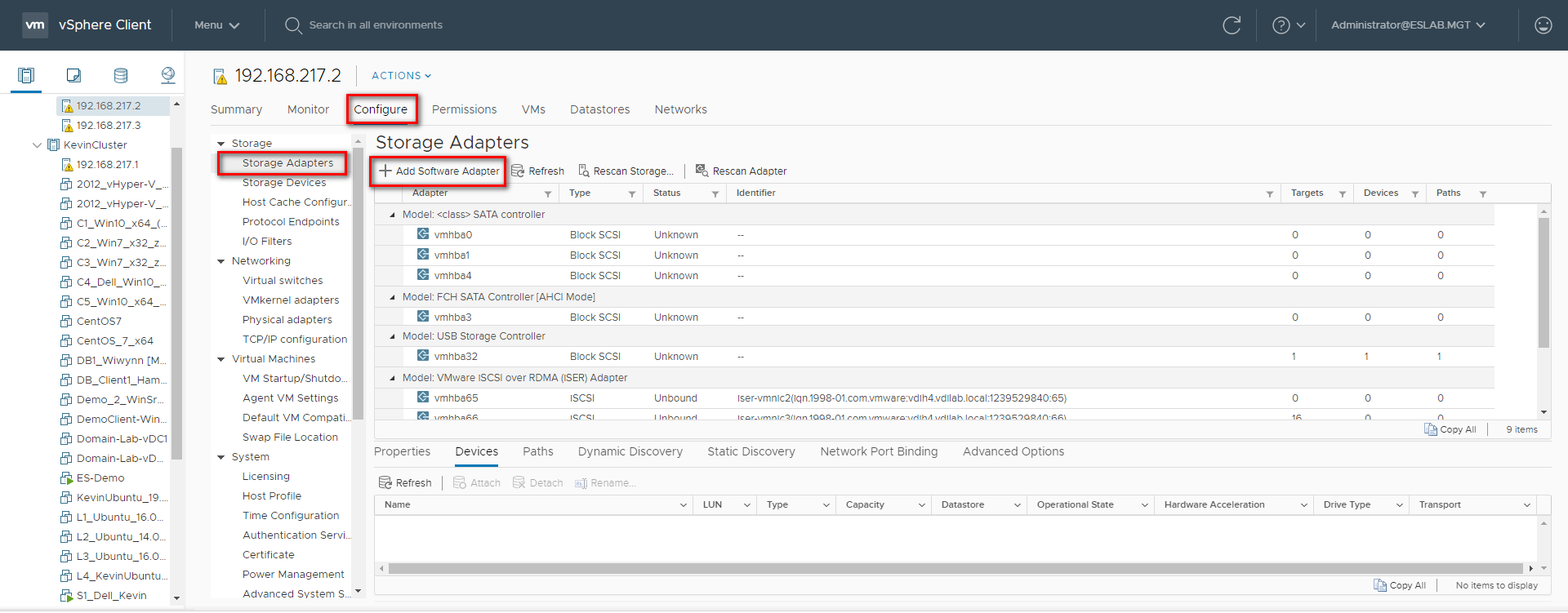
Step 1: Log in to the vSphere Web Client and select a host from the inventory panel. Go to the “Configure” tab and then the “Storage Adapters” tab. Click “+ Add Software Adapter” to add a new storage adapter.
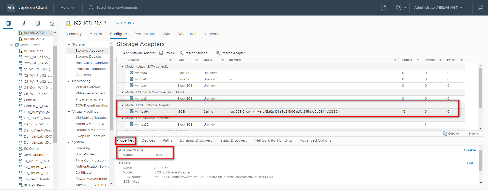
Step 2: A new software iSCSI adapter will be added to the Storage Adapter list. Select the software iSCSI adapter on the list and click “Properties” to ensure the adapter is enabled.
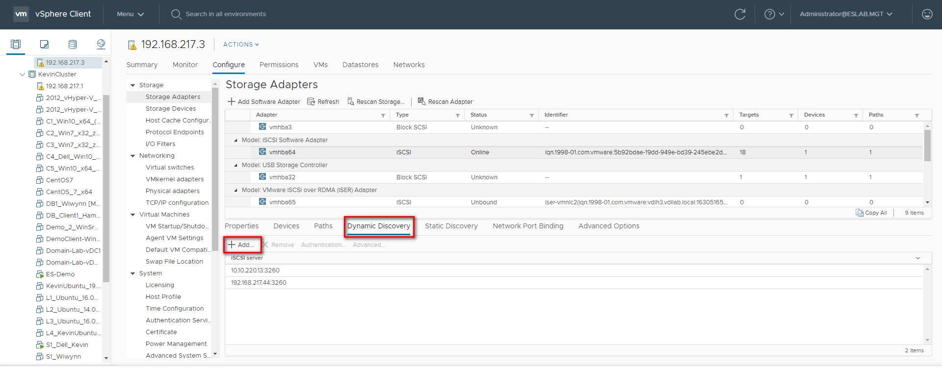
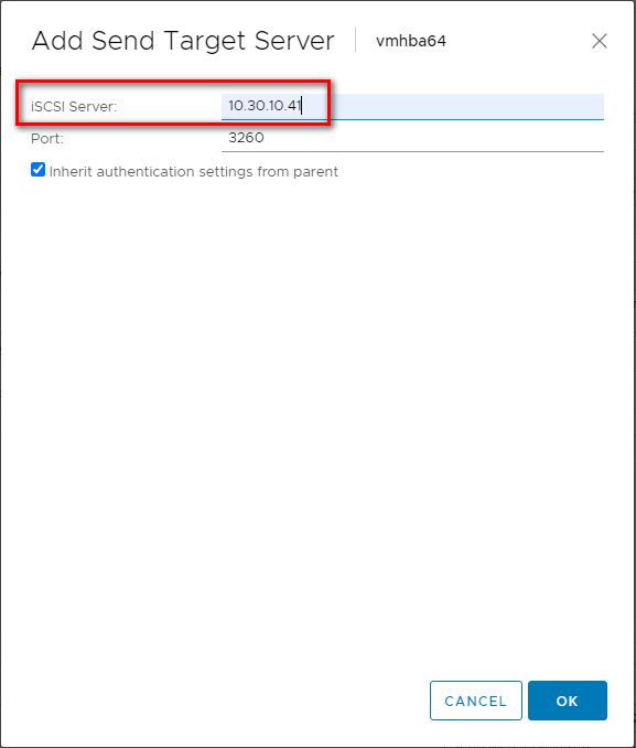
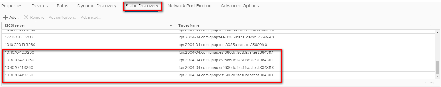
Step 3: Click “Dynamic Discovery” and then click “Add…” to add the data ports’ IP addresses of both controllers. Then go to “Static Discover” tab to view the names and IP addresses of these targets. If you remove a static target added by dynamic discovery, the target might be returned to the list the next time a rescan happens, the HBA is reset, or the host is rebooted.
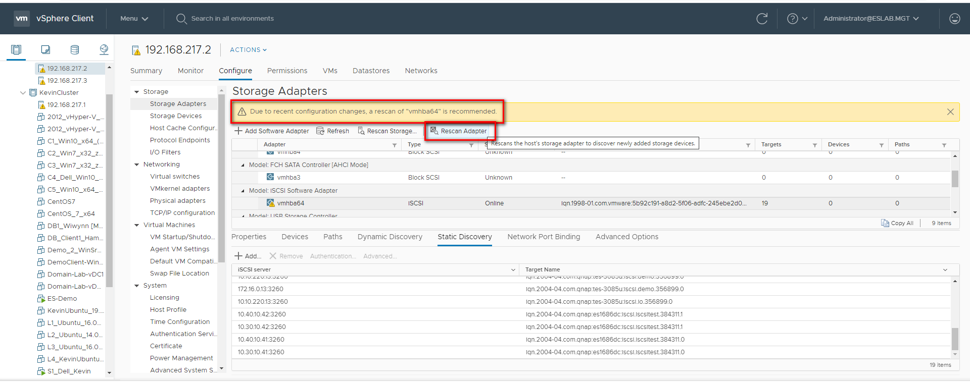
Step 4: Click “Rescan” to scan the newly added devices.
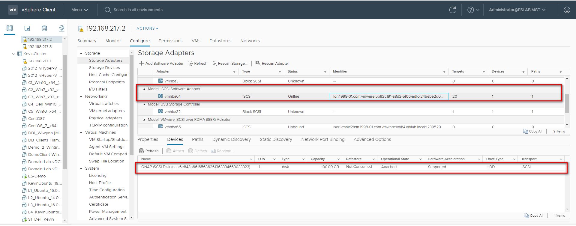
Step 5: You can now find the corresponding iSCSI device for the added iSCSI adapter.
Configure the Path for iSCSI Connection
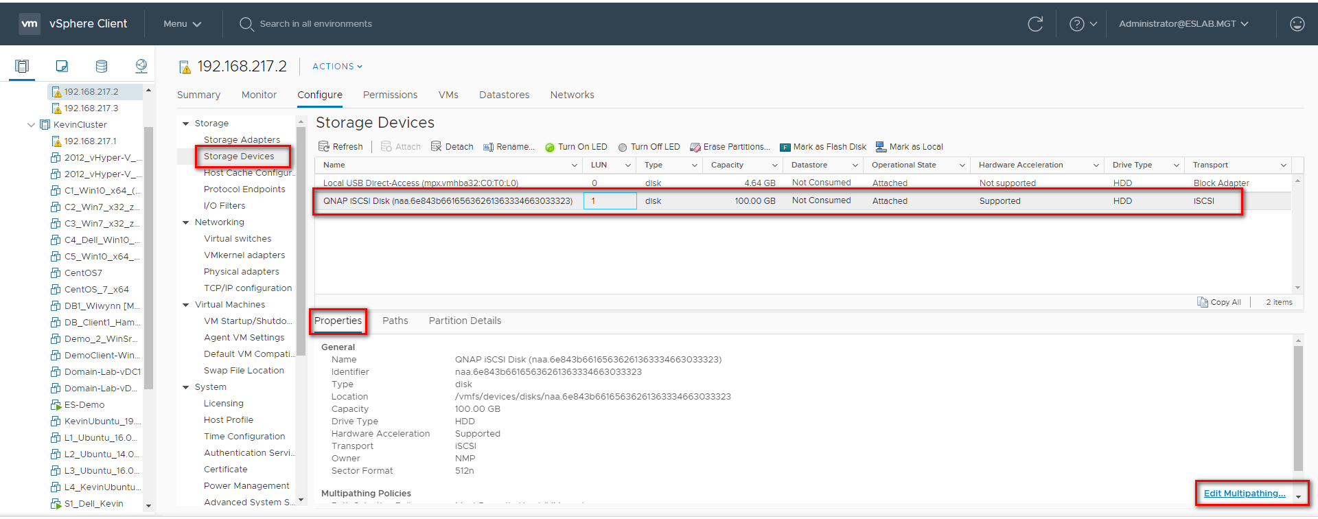
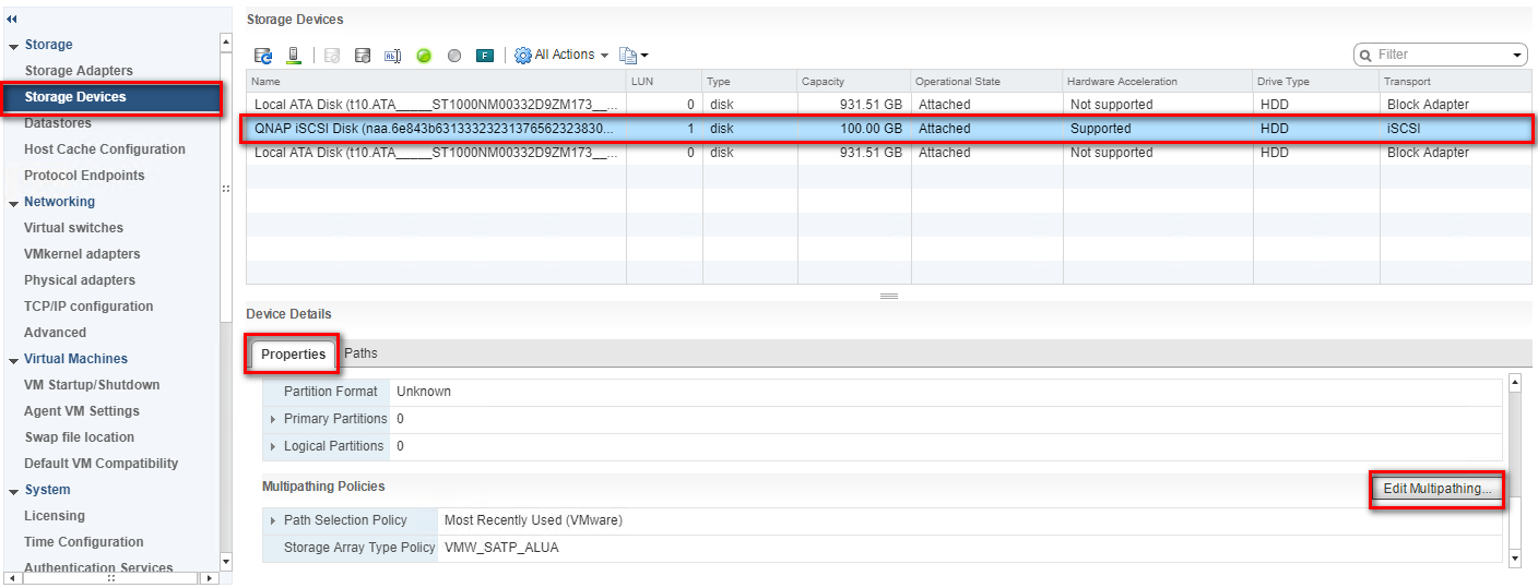
Step 6: Click “Storage Devices”, select the iSCSI Disk, and then click “Properties” > “Edit Multipathing…”
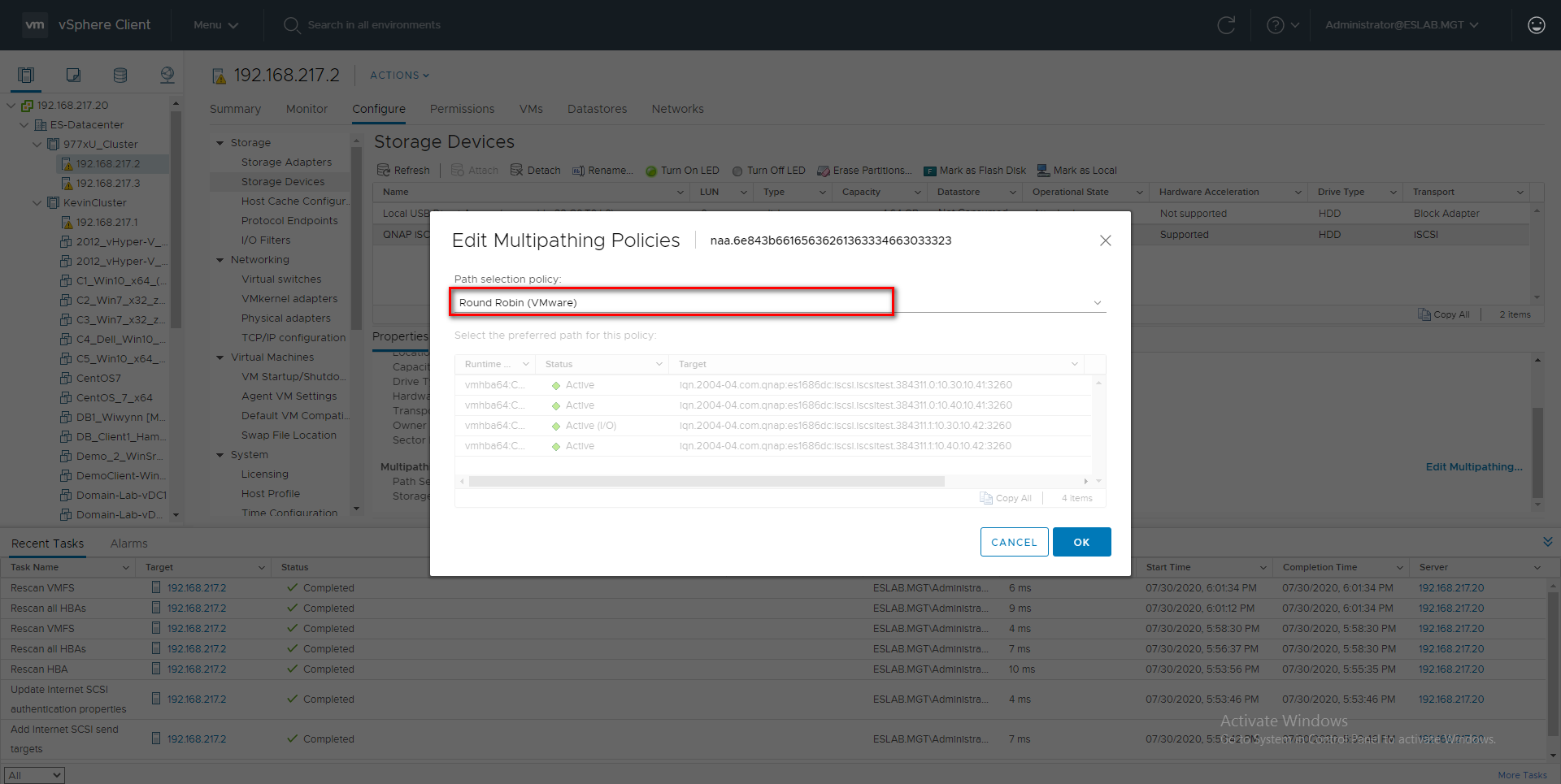
Step 7: Select “Round Robin (VMware)*” in Path selection policy, then select one path as the preferred path and click “OK”.
Create a VMFS Datastore in the vSphere Client
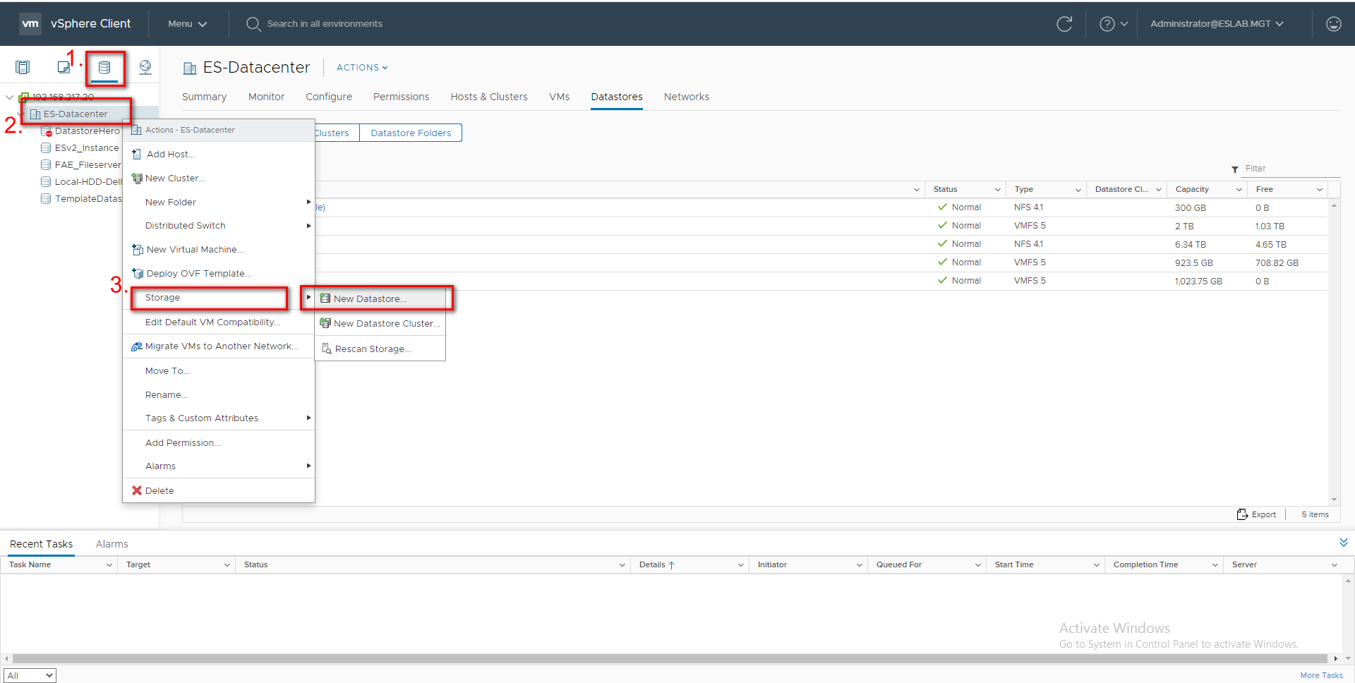
Step 8: Go to the “Storage” tab and right click on the Datacenter. Select “Storage” > “New Datastore…”.
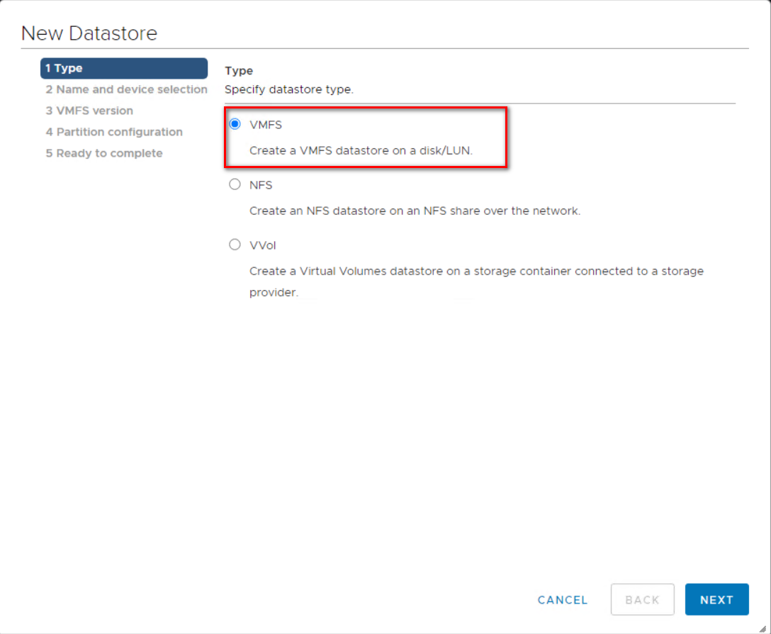
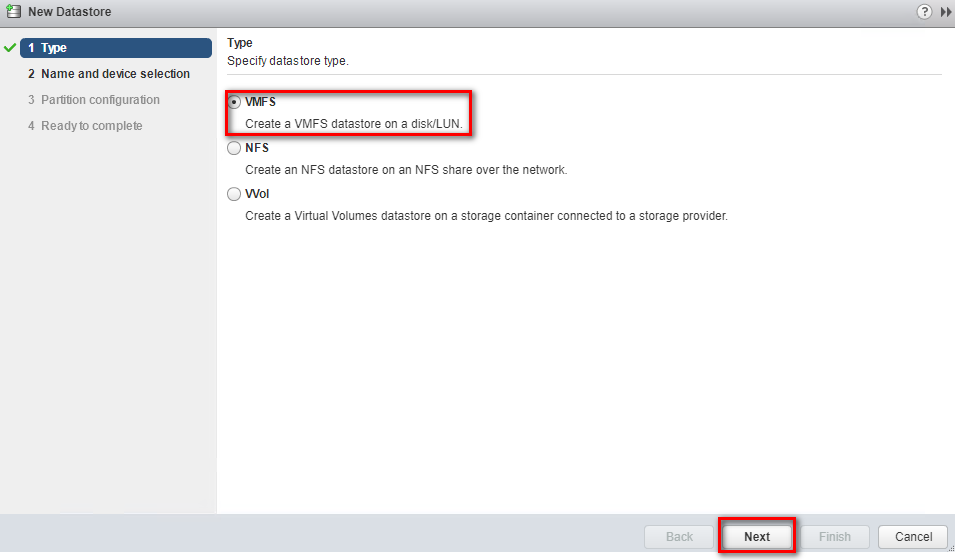
Step 9: Select “VMFS” as the Type and click “Next”
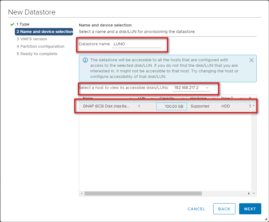
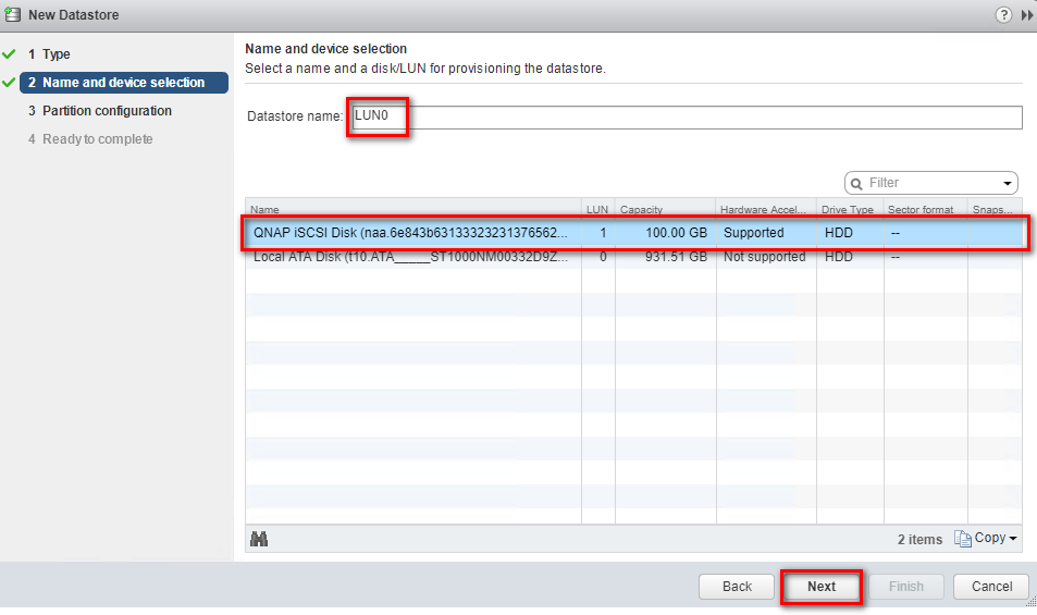
Step 10: Enter a name for the datastore, select a host, and select the iSCSI device to use for your datastore.
Click “Next”.
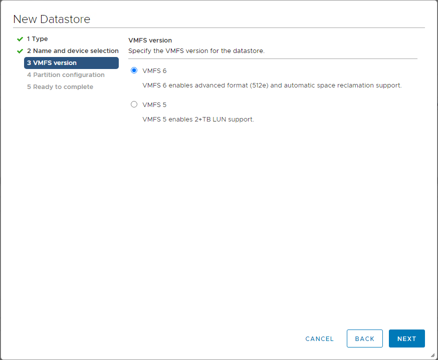
Step 11: Select VMFS 6 or VMFS 5 and click “Next”.
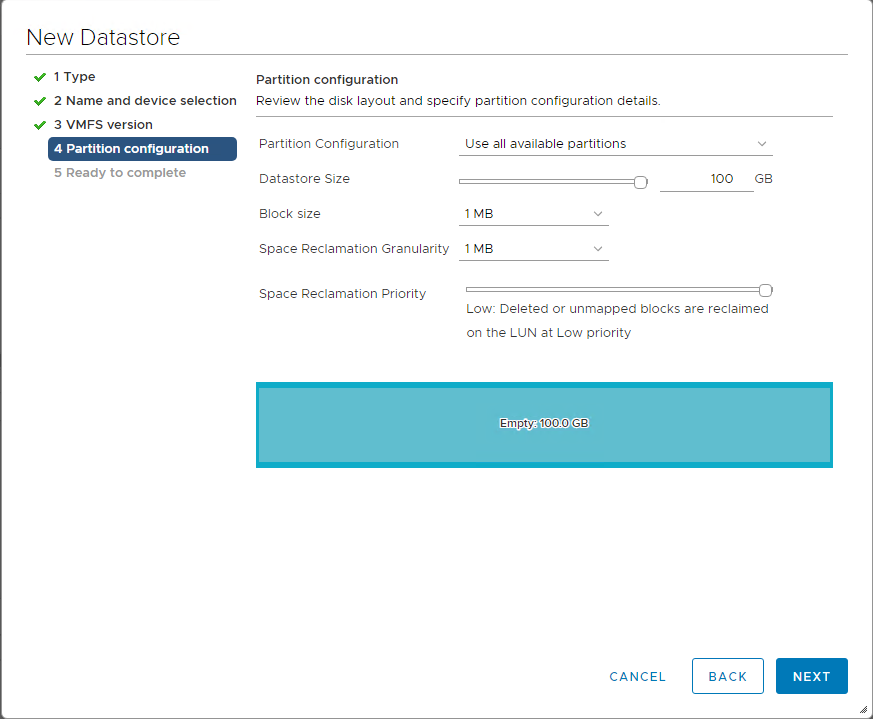
Step 12: Adjust the capacity values and click “Next”. By default, the entire space on the storage device is available.
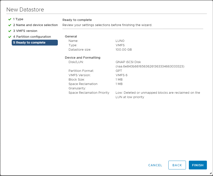
Step 13: Review the datastore configuration information and click “Finish”.
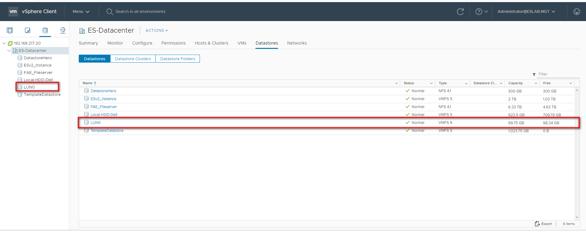
Step 14: The datastore on the iSCSI-based storage device will be listed.
For VMWare vSphere Web Client 6.5
Server and Storage Network Settings
|
Server Network Settings |
||
|---|---|---|
|
Role |
IP |
Description |
|
ESXi host |
192.168.1.50 |
VMware ESXi host |
|
Data Network 1 |
8.8.1.50 |
10G Data port 1 in ESXi host |
|
Data Network 2 |
8.8.2.50 |
10G Data port 2 in ESXi host |
|
Storage Network Settings |
||
|---|---|---|
|
Setting |
Value |
Description |
|
SCA Management IP |
192.168.1.12 |
Management IP of controller A |
|
SCA Ethernet1 IP |
8.8.1.13 |
Data port 1 IP of controller A |
|
SCA Ethernet2 IP |
8.8.2.13 |
Data port 2 IP of controller A |
|
SCB Management IP |
192.168.1.13 |
Management IP of controller B |
|
SCB Ethernet1 IP |
8.8.1.14 |
Data port 1 IP of controller B |
|
SCB Ethernet2 IP |
8.8.2.14 |
Data port 2 IP of controller B |
|
Pool allocate to SCB |
Pool2 |
RAID6 pool at controller B |
With the information listed in the above table, assuming a 100GB LUN is deployed on ES dual controller B (SCB), it can be mounted using the following steps on the ESXi host.
Add iSCSI Targets on VMware ESXi Hosts
Step 1: Log in to the vSphere Web Client and select a host from the inventory panel. Go to the “Configure” tab and then the “Storage Adapters” tab. Click “+” to add a new storage adapter.
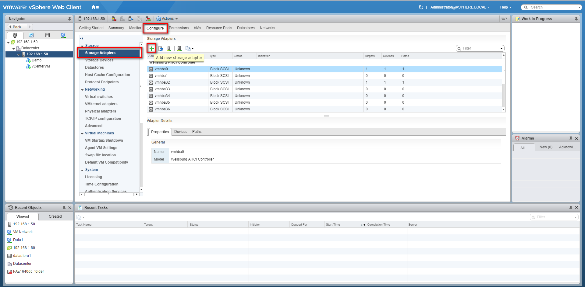
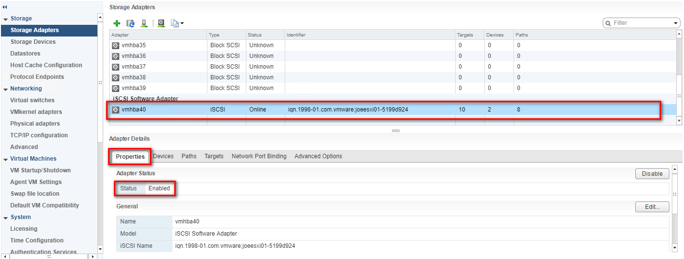
Step 2: A new software iSCSI adapter will be added to the Storage Adapter list. Select the new software iSCSI adapter in the list and click “Properties” to ensure the adapter is enabled.
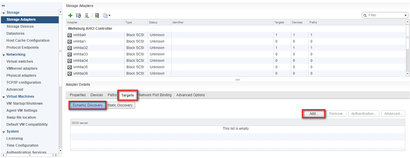
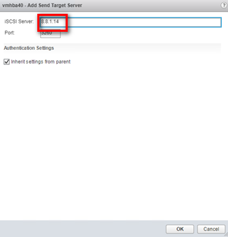
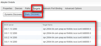
Step 3: After enabling the adapter, you must set up target discovery addresses so that the iSCSI adapter can determine which storage resource on the network is available for access. Go to the “Targets” tab, click “Dynamic Discovery” and then click “Add...” to add the data ports’ IP addresses of both controllers. Then go to the “Static Discovery” tab to view the names and IP addresses of these targets. If you remove a static target added by dynamic discovery, the target might be returned to the list the next time a rescan happens, the HBA is reset, or the host is rebooted.
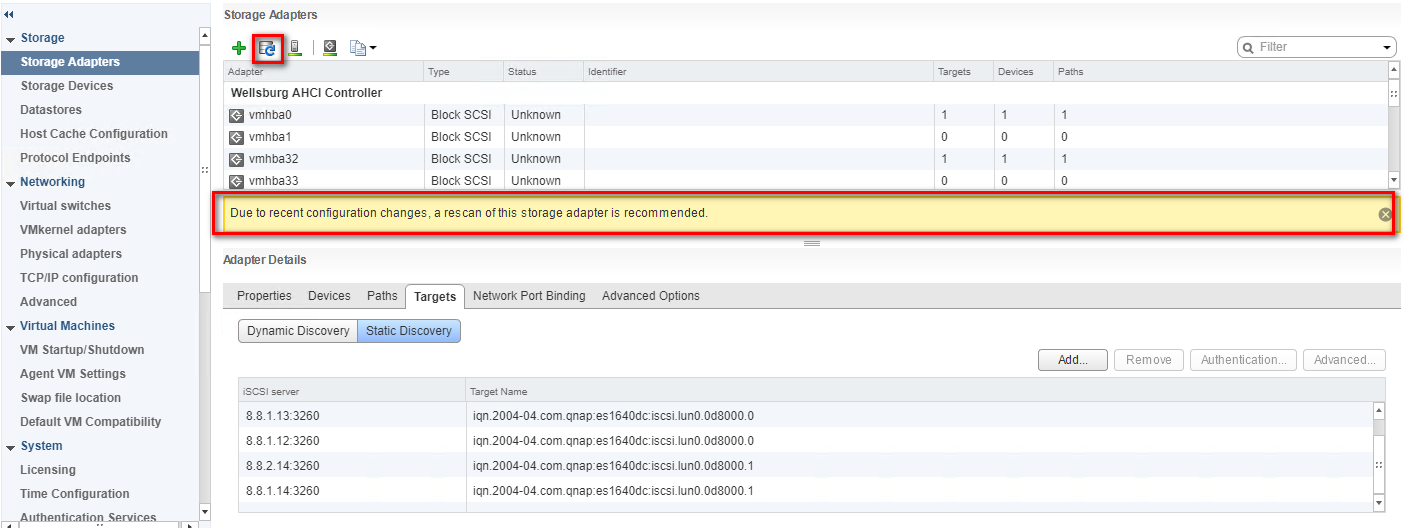
Step 4: Click “Rescan” to scan the newly added devices.
Note:
If CHAP is enabled in the QES NAS iSCSI Target, you should have the same configuration in “CHAP…” in the “Add Send Target Server” window.
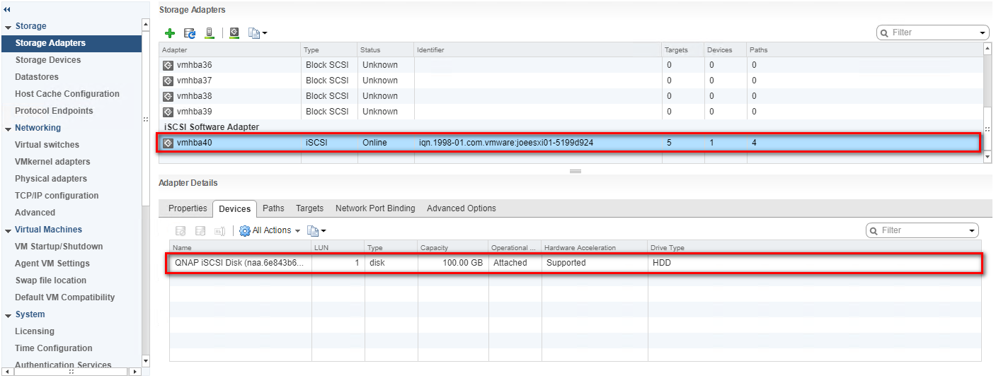
Step 5: You can now find the corresponding iSCSI device for the added iSCSI adapter.
Configure the Path for iSCSI Connection
Step 6: Click “Storage Devices”, select the iSCSI Disk, and then click “Properties” > “Edit Multipathing…”
Step 7: Select “Fixed (VMware)” in Path selection policy, then select one path as the preferred path. Click “OK”.
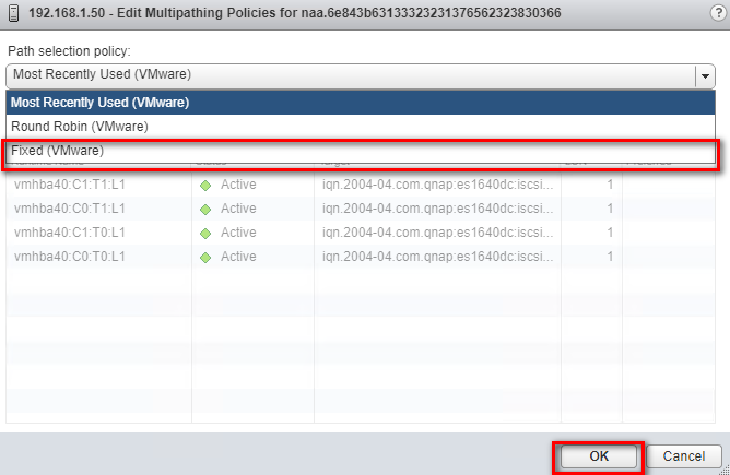
Note:
For better iSCSI performance, select the path or Ethernet port which belongs to the Storage Controller that owns the iSCSI LUN. In our example, we chose ports (8.8.1.14/8.8.2.14) which belong to SCB on which Pool 2 was created.
The data port shows after the Target name.
For example: iqn.2004-04.com.qnap:es1640dc:iscsi.lun0.0d8000:8.8.1.14:3260
Create a VMFS Datastore in the vSphere Client
Step 8: Go to the “Configure” tab and then the “Datastores” tab. Click the “Create a new datastore” icon.

Step 9: Select “VMFS” as the Type and click “Next”
Step 10: Enter a name for the datastore and select the iSCSI device to use for your datastore. Click “Next”.
Step 11: Adjust the capacity values and click “Next”. By default, the entire space on the storage device is available.
Step 12: Review the datastore configuration information and click “Finish”.

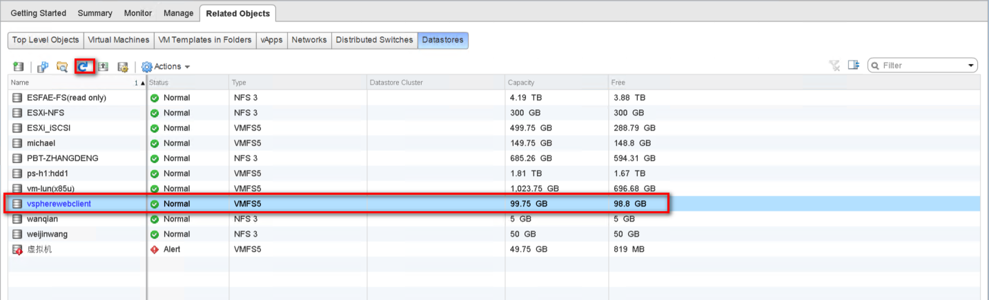
Step 13: Click the “Recalculate” icon and the datastore on the iSCSI-based storage device will be listed.
For VMWare vSphere Web Client 6.0
Server and Storage Network Settings
|
Server Network Settings |
||
|---|---|---|
|
Role |
IP |
Description |
|
ESXi host |
172.17.23.116 |
VMware ESXi host |
|
Data Network 1 |
10.10.10.1 |
10G Data port 1 in ESXi host |
|
Data Network 2 |
10.10.20.1 |
10G Data port 2 in ESXi host |
|
Storage Network Settings |
||
|---|---|---|
|
Setting |
Value |
Description |
|
SCA Management IP |
172.17.23.111 |
Management IP of controller A |
|
SCA Ethernet1 IP |
10.10.10.111 |
Data port 1 IP of controller A |
|
SCA Ethernet2 IP |
10.10.20.111 |
Data port 2 IP of controller A |
|
SCB Management IP |
172.17.23.112 |
Management IP of controller B |
|
SCB Ethernet1 IP |
10.10.10.112 |
Data port 1 IP of controller B |
|
SCB Ethernet2 IP |
10.10.20.112 |
Data port 2 IP of controller B |
|
Pool allocate to SCB |
Pool2 |
RAID6 pool at controller B |
With the information listed in the table above, assuming a 100GB LUN is deployed on ES dual controller B (SCB), it can be mounted using the following steps on the ESXi host.
Add iSCSI Targets on VMware ESXi Hosts
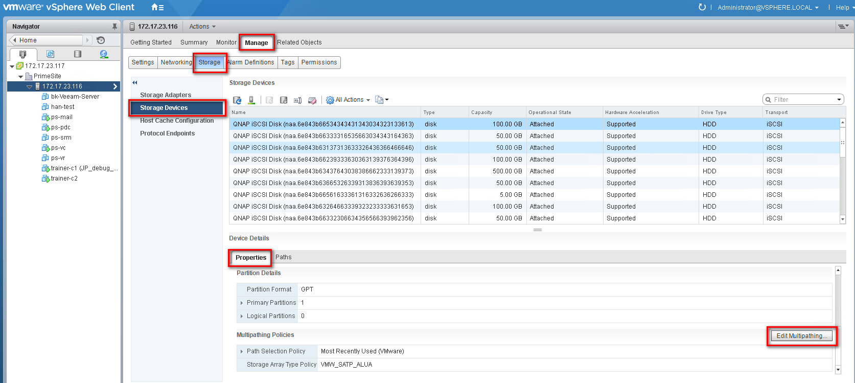
Step 1: Log in to the vSphere Web Client and select a host from the inventory panel. Go to the “Manage” tab and then the “Storage” tab. Click “Storage Adapters” then click “+” to add a storage adapter.

Step 2: A new software iSCSI adapter will be added to the Storage Adapter list. Select the software iSCSI adapter on the list and click “Properties”.
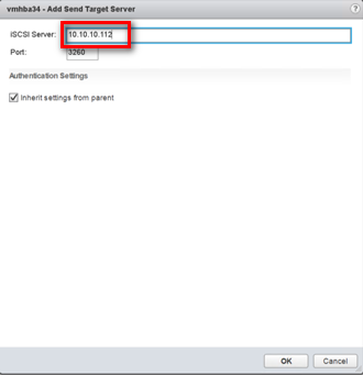
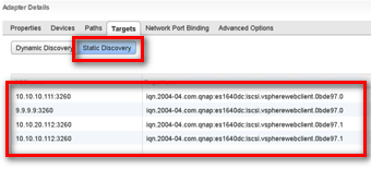
Step 3: Enable the adapter and set up target discovery addresses so that the iSCSI adapter can determine which storage resource on the network is available. Go to the “Targets” tab, click “Dynamic Discovery” and “Add...” to add the data ports’ IP addresses of both controllers. Then go to the “Static Discovery” tab to view the names and IP addresses of these targets. If you remove a static target added by dynamic discovery, the target might be returned to the list the next time a rescan happens, the HBA is reset, or the host is rebooted.
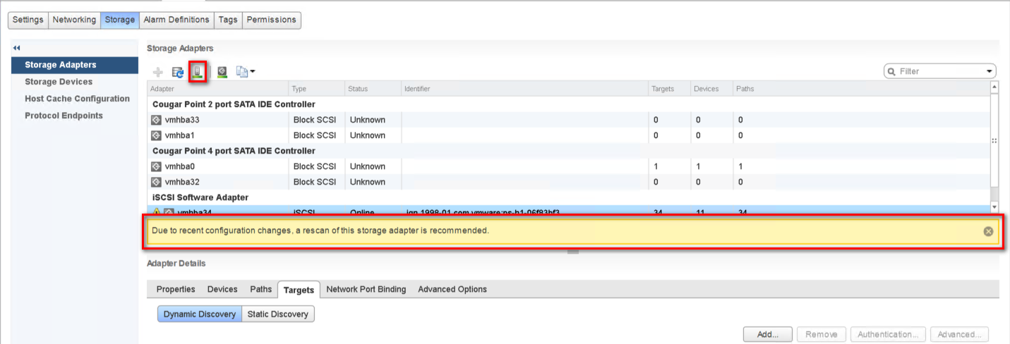
Step 4: Click “Rescan” to scan the newly added devices.
Note:
If CHAP is enabled in the QES NAS iSCSI Target, you should have the same configuration in “CHAP…” in the “Add Send Target Server” window.
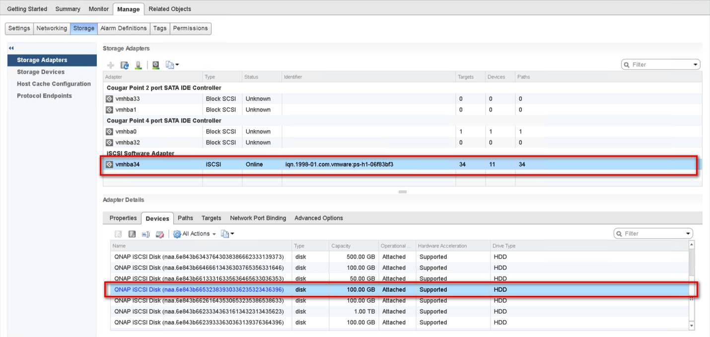
Step 5: You can now find the corresponding iSCSI device for the added iSCSI adapter.
Configure the Path for iSCSI Connection
Step 6: Click “Storage Devices”, select the iSCSI Disk, and then click “Properties” > “Edit Multipathing…”
Step 7: Select “Fixed (VMware)” in Path selection policy, then select one path as the preferred path. Click “OK”.
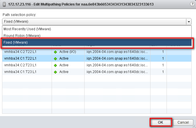
Note:
For better iSCSI performance, select the path or Ethernet port which belongs to the Storage Controller that owns the iSCSI LUN. In our example, we chose ports (8.8.1.14/8.8.2.14) which belong to SCB on which Pool 2 was created.
The data port shows after the Target name.
For example: iqn.2004-04.com.qnap:es1640dc:iscsi.lun0.0d8000:8.8.1.14:3260
Create a VMFS Datastore in the vSphere Client
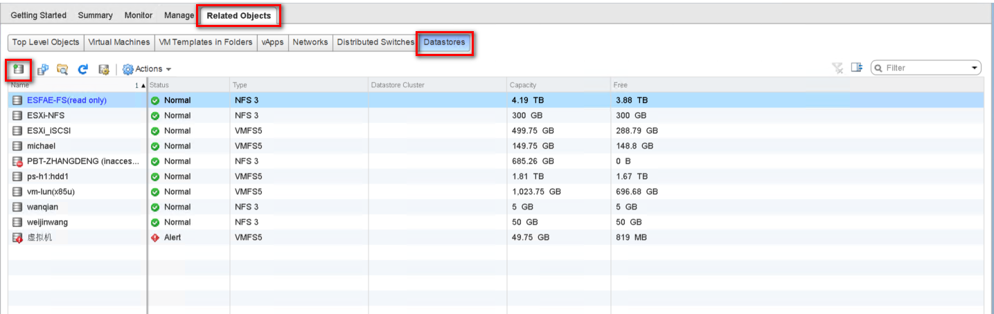
Step 8: Go to the “Configure” tab and then the “Datastores” tab. Click the “Create a new datastore” icon.
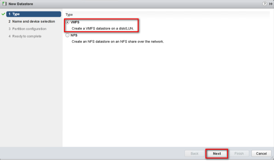
Step 9: Select “VMFS” as the Type and click “Next”
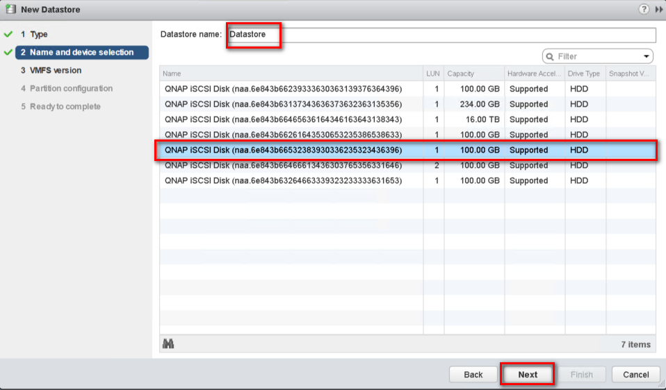
Step 10: Enter a name for the datastore and select the iSCSI device to use for your datastore. Click “Next”.
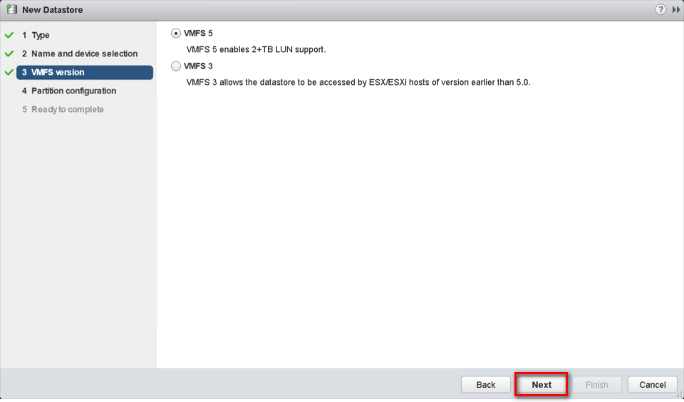
Step 11: Choose the proper VMFS version and click “Next”.
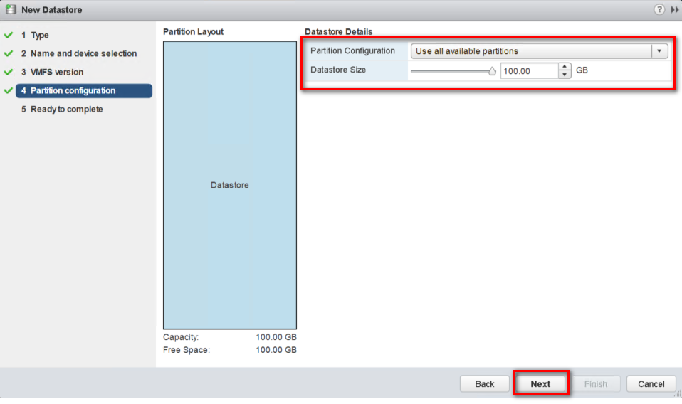
Step 12: Adjust the capacity values and click “Next”. By default, the entire space on the storage device is available.
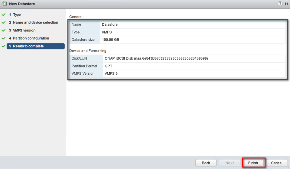
Step 13: Review the datastore configuration information and click “Finish”.
Step 14: Click the “Recalculate” icon , and the datastore on the iSCSI-based storage device will be listed.
For VMware vSphere Windows Version
Server and Storage Network Settings
|
Server Network Settings |
||
|---|---|---|
|
Role |
IP |
Description |
|
ESXi host |
192.168.217.1 |
VMware ESXi host |
|
Data Network 1 |
10.10.10.1 |
10G Data port 1 in ESXi host |
|
Data Network 2 |
10.10.20.1 |
10G Data port 2 in ESXi host |
|
Storage Network Settings |
||
|---|---|---|
|
Setting |
Value |
Description |
|
SCA Management IP |
192.168.217.61 |
Management IP of controller A |
|
SCA Ethernet1 IP |
10.10.10.61 |
Data port 1 IP of controller A |
|
SCA Ethernet2 IP |
10.10.20.61 |
Data port 2 IP of controller A |
|
SCB Management IP |
192.168.217.62 |
Management IP of controller B |
|
SCB Ethernet1 IP |
10.10.10.62 |
Data port 1 IP of controller B |
|
SCB Ethernet2 IP |
10.10.20.62 |
Data port 2 IP of controller B |
|
Pool allocate to SCA |
Pool1 |
RAID6 pool at controller A |
With the information listed in the above table, assuming a 100GB LUN is deployed on ES dual controller A (SCA), it can be mounted using the following steps on the ESXi host.
Add iSCSI Targets on VMware ESXi Hosts
Step 1: Log in to vSphere Client and select a host from the inventory panel. Go to the “Configuration” tab and click “Storage Adapters” in the Hardware panel. Click “Add…” on the top right of the window to add a storage adapter.
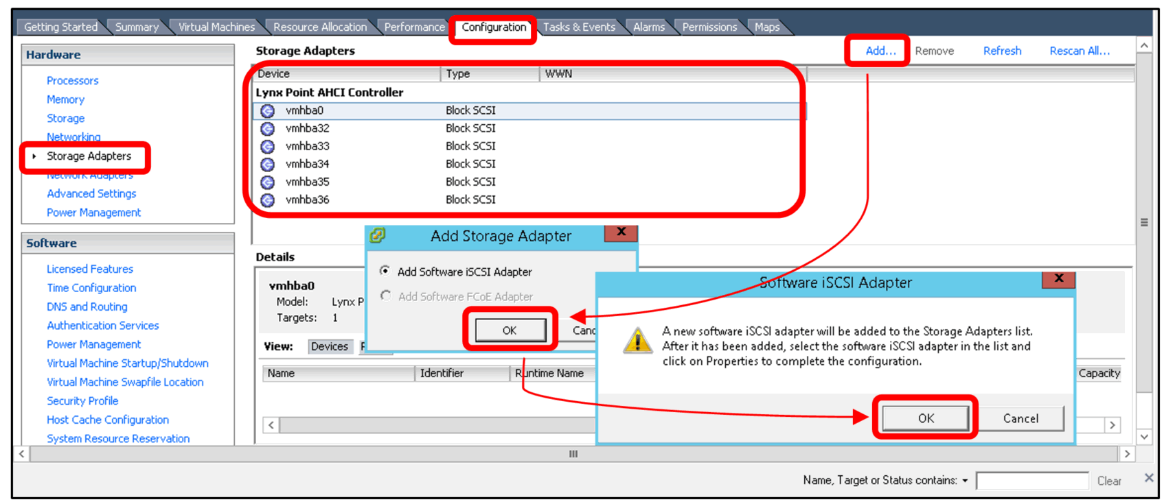
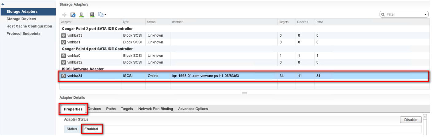
Step 2: A new software iSCSI adapter will be added to the Storage Adapter list. Select the new software iSCSI adapter on the list and click “Properties”.
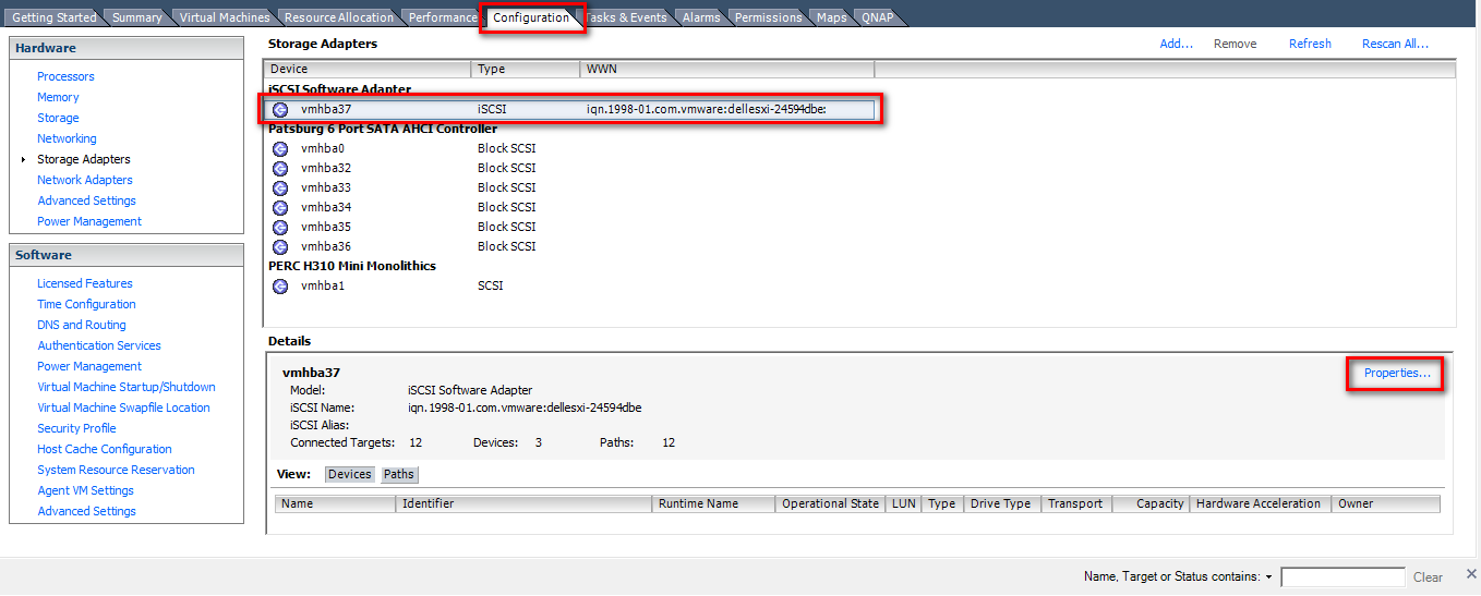
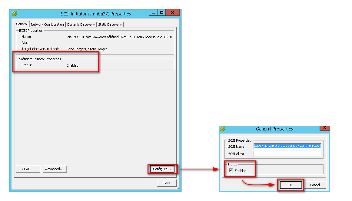
Step 3: Ensure the adapter is enabled. If not, click “Configure…”, check "Enabled" and click “OK”.
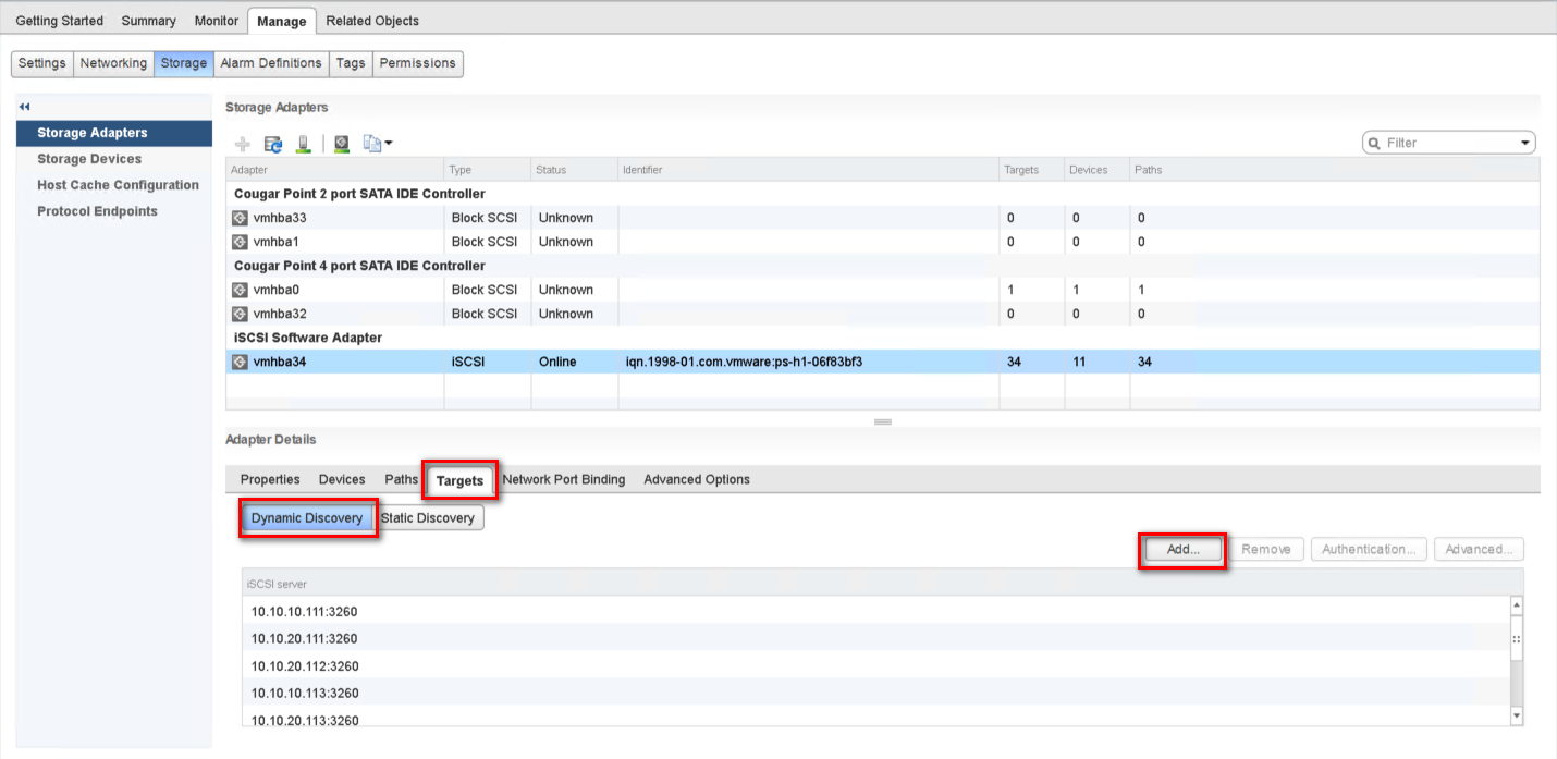
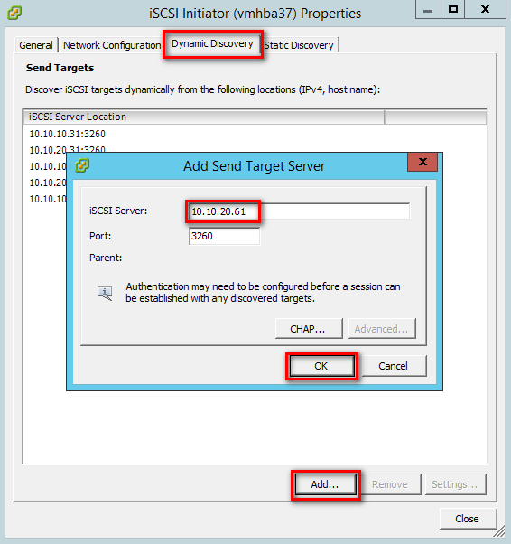
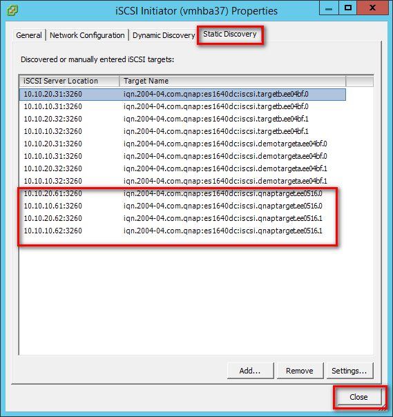
Step 4: After enabling the adapter, you must set up target discovery addresses so that the iSCSI adapter can determine which storage resource on the network is available. Go to the “Dynamic Discovery” tab and click “Add...” to add the data ports’ IP addresses of both controllers. Then go to the “Static Discovery” tab to view the names and IP addresses of these targets.
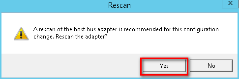
Step 5: Click “Close” to close the Properties window. The “Rescan” window will appear. Click “Yes”.
Note:
If CHAP is enabled in the QES NAS iSCSI Target, you should have the same configuration in “CHAP…” in the “Add Send Target Server” window.
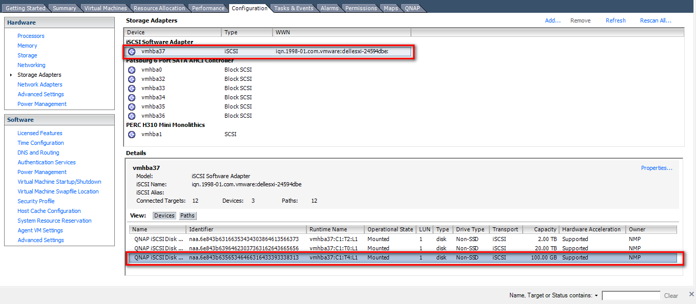
Step 6: You can now find the corresponding iSCSI device for the added iSCSI adapter.
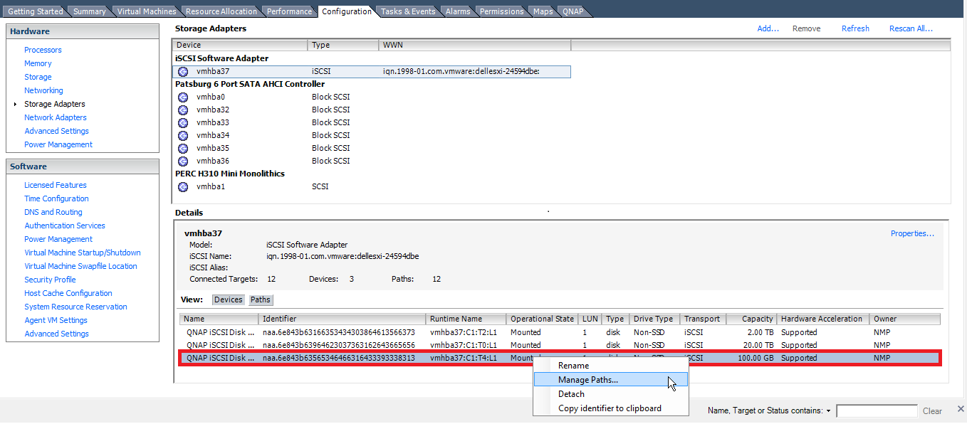
Configure the Path for iSCSI Connection
Step 7: Right-click on an iSCSI disk and select “Manage Paths…”
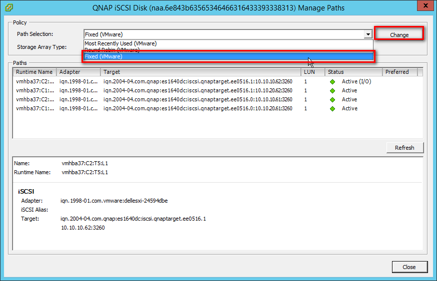
Step 8: Select “Fixed (VMware)” from the “Path Selection” drop-down menu as the path selection policy. Then click “Change” to apply the changes.
Step 9: Specify the preferred path by right-clicking the path you want to assign as the preferred path and select “Preferred”. Then click “OK” to save your settings and exit the dialog box.
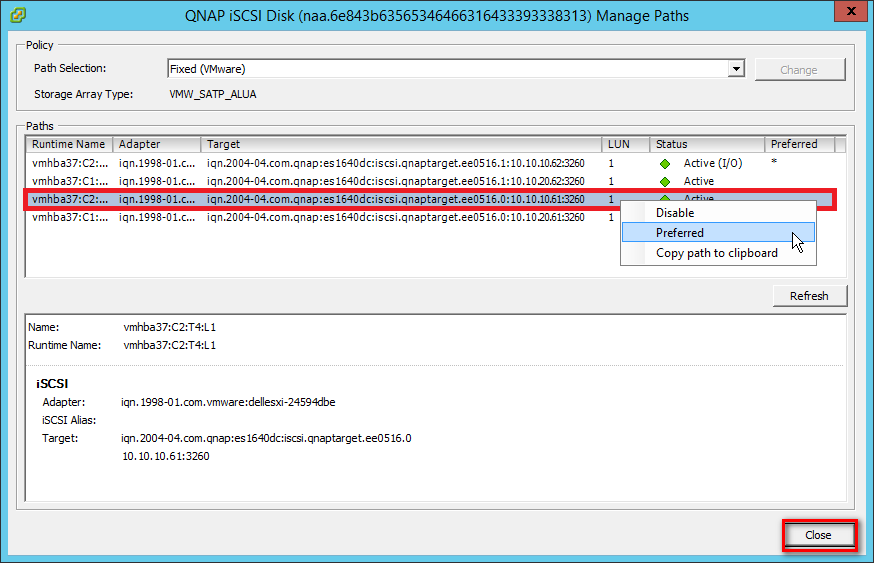
Note:
For better iSCSI performance, select the path or Ethernet port which belongs to the Storage Controller that owns the iSCSI LUN. In our example, we chose ports (10.10.10.61/10.10.20.61) which belong to SCA on which Pool 1 was created.
The data port shows below the Target name.
Create a VMFS Datastore in the vSphere Client
Before creating datastores, use the “Rescan” function for the adapters to discover newly added storage devices.
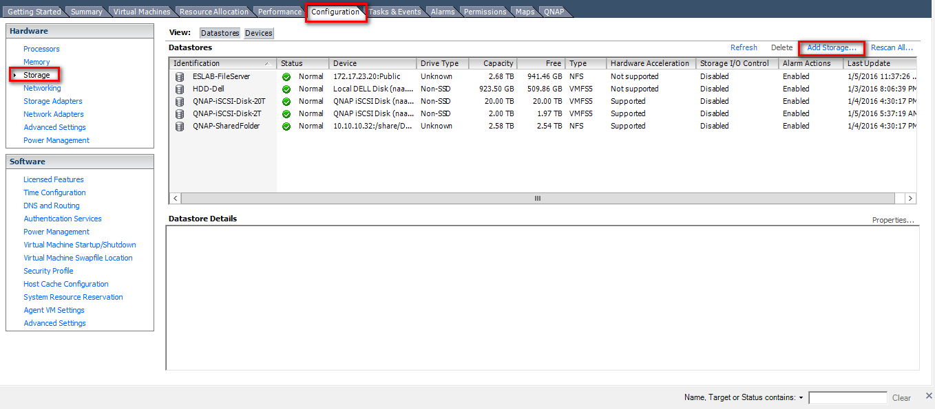
Step 10: Go to the “Configuration” tab and click “Storage” in the Hardware panel. Then click “Datastores” > “Add Storage”.
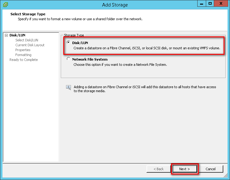
Step 11: Select “Disk/LUN” as the Storage Type and click “Next”.
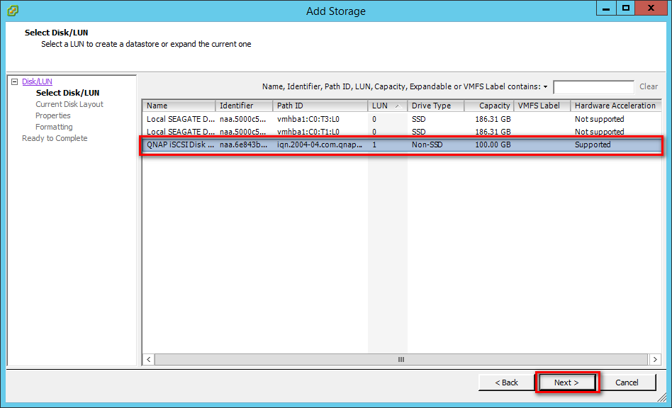
Step 12: Select the iSCSI device to use for your datastore and click “Next”.
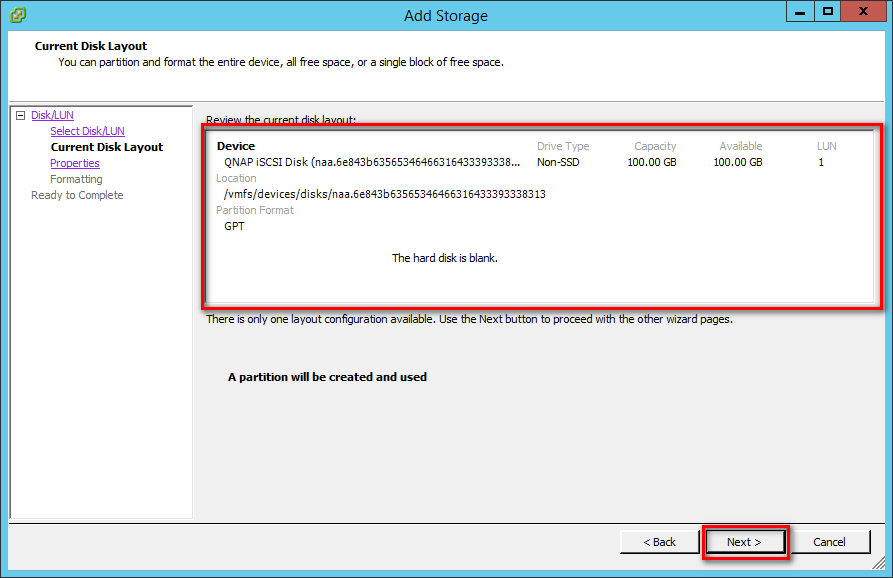
Step 13: The “Current Disk Layout” page presents the information about this iSCSI disk and its space usage. Confirm the settings and click “Next”.
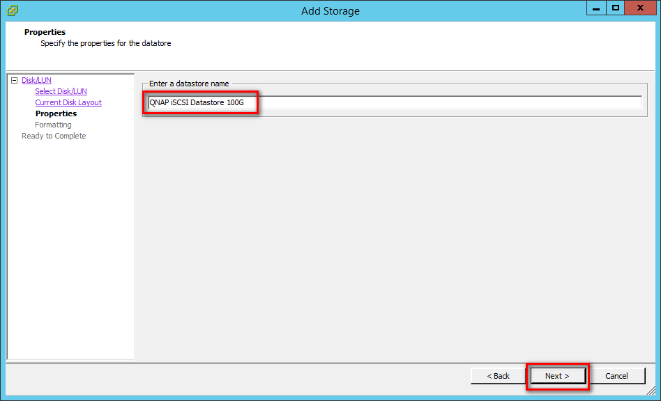
Step 14: Enter a name for the datastore and click “Next”.
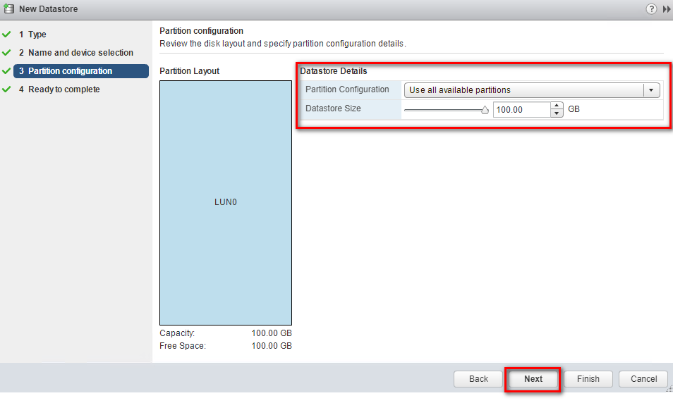
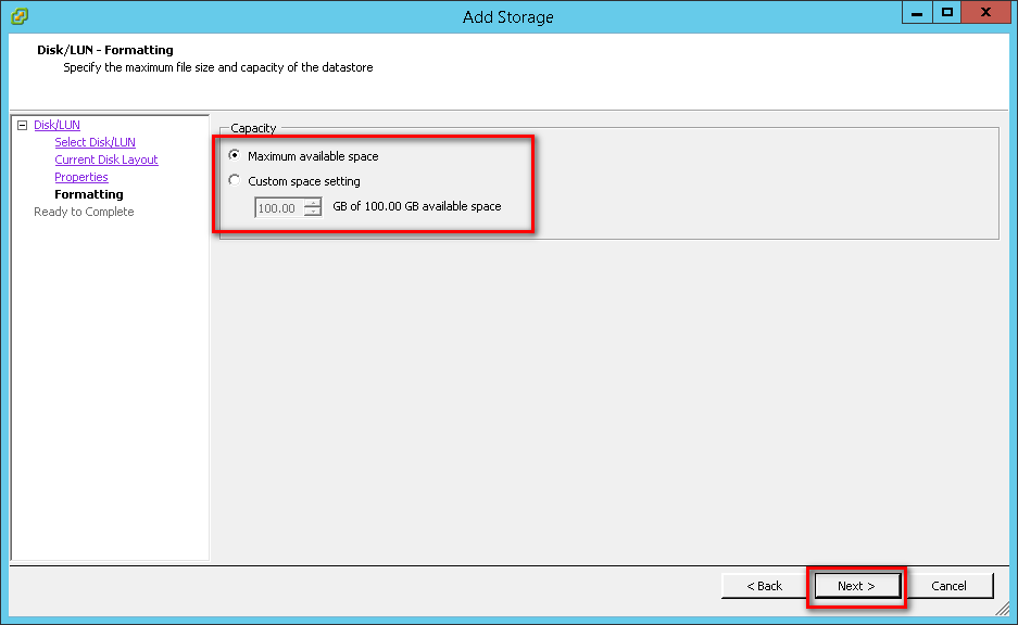
Step 15: Adjust the capacity values and click “Next”. By default, the entire space on the storage device is available.
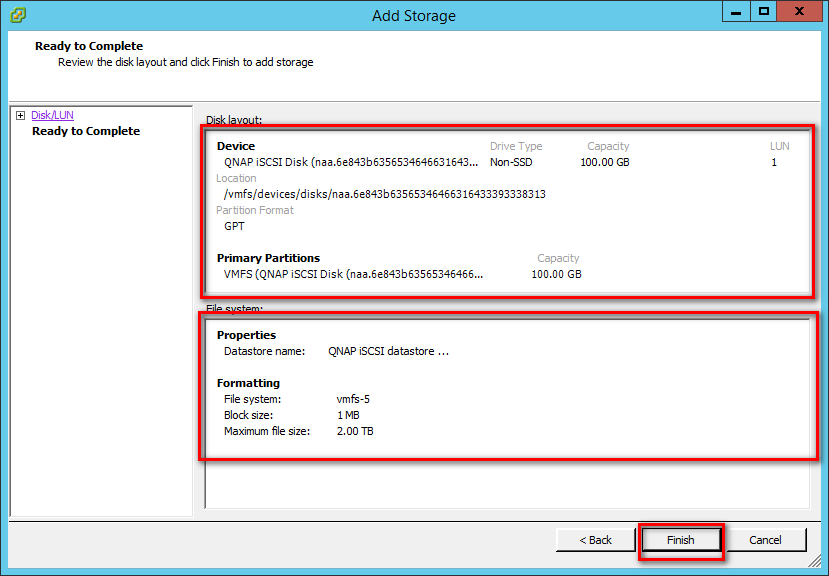
Step 16: Review the datastore configuration information and click “Finish”.
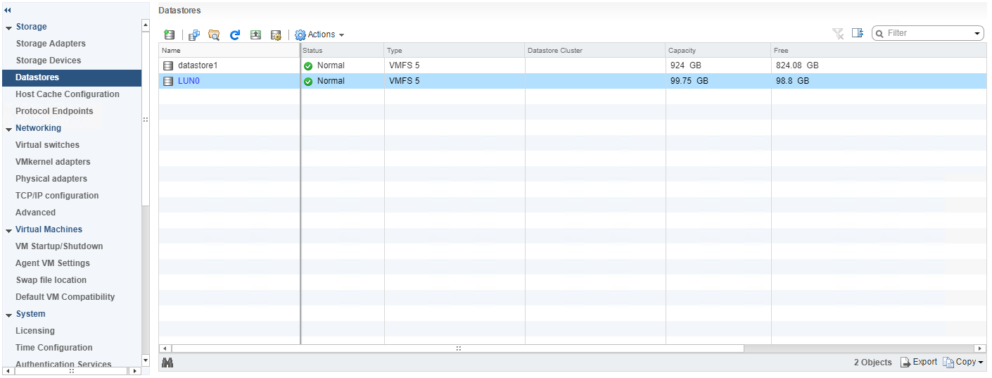
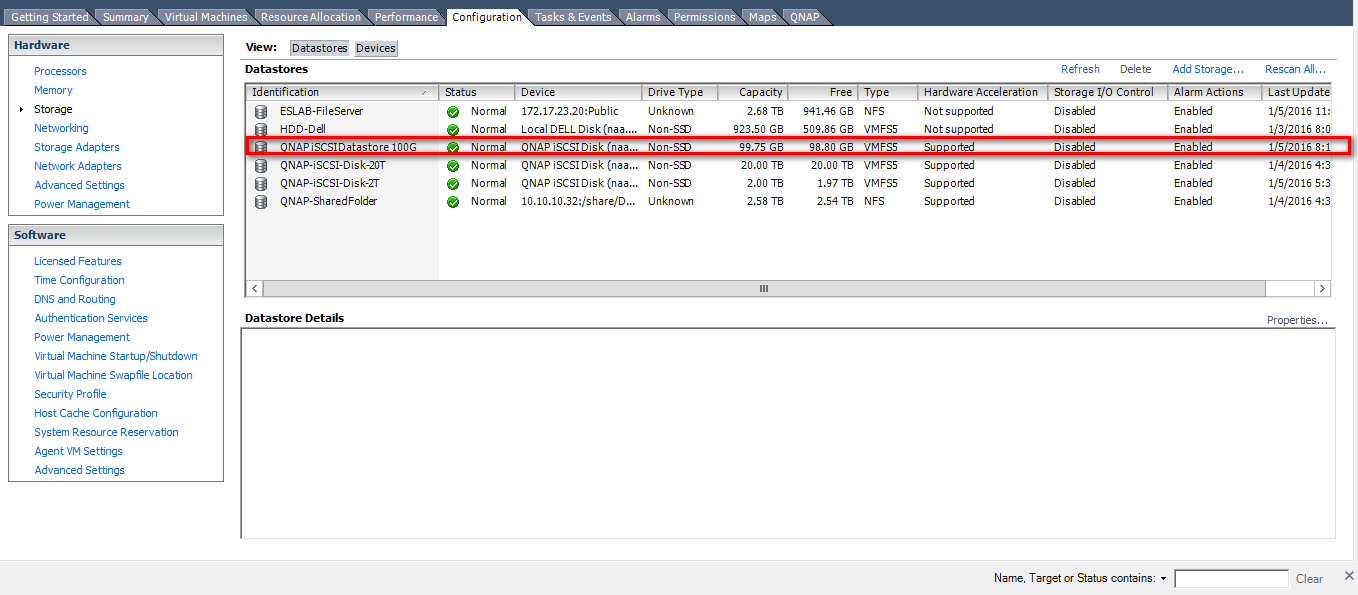
Step 17: The newly-created datastore on the iSCSI-based storage device will be listed.
Additional References
For more tutorials related to VMware, please refer to the following links:


